Operator’s Manual SRM-3020U Grass Trimmer/ Brushcutter The engine exhaust from this product contains chemicals known to the State of California to cause cancer, birth defects, or other reproductive harm. Read and understand all provided literature before use. Failure to do so could result in serious injury. This product complies with CAN ICES-2/NMB-2. X7502350201 © 11/2018 ECHO Inc.
TABLE OF CONTENTS SRM-3020U TABLE OF CONTENTS Introduction ................................................................................................. 4 Servicing Information .................................................................................. 4 Parts/Serial Number............................................................................. 4 Service ................................................................................................. 5 ECHO Consumer Product Support .......
SRM-3020U TABLE OF CONTENTS Cooling System ................................................................................. Exhaust System ................................................................................ Carburetor Adjustment ...................................................................... Lubrication ......................................................................................... Nylon Line Head Disassembly Instructions .......................................
INTRODUCTION SRM-3020U INTRODUCTION Specifications, descriptions and illustrative material in this literature are as accurate as known at the time of publication, but are subject to change without notice. Illustrations may include optional equipment and accessories, and may not include all standard equipment. Read and understand all provided literature. Literature contains specifications and information for safety, operation, maintenance, storage and assembly specific to this product.
SRM-3020U SAFETY Service Service of this product during the warranty period must be performed by an Authorized ECHO Service Dealer. For the name and address of the Authorized ECHO Service Dealer nearest you, ask your retailer or call: 1-800-432-ECHO (3246). Dealer information is also available on our Web Site www.echo-usa.com. When presenting your unit for Warranty service/ repairs, proof of purchase is required.
SAFETY SRM-3020U The safety alert symbol accompanied by the word “DANGER” calls attention to an act or condition which WILL lead to serious personal injury or death if not avoided. The safety alert symbol accompanied by the word “WARNING” calls attention to an act or condition which CAN lead to serious personal injury or death if not avoided.
SRM-3020U SAFETY Symbol Description Symbol Description Safety/Alert Emergency Stop Hot Surface Fuel and Oil Mixture AVOID KICKOUT Keep Bystanders At Least 15 m (50 ft.
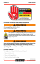
SAFETY SRM-3020U Personal Condition and Safety Equipment Cancer and Reproductive Harm www.P65Warnings.ca.gov The muffler or catalytic muffler and surrounding cover may become extremely hot. Always keep clear of exhaust and muffler area, otherwise serious personal injury may occur. Users of this product risk injury to themselves and others if the unit is used improperly and/or safety precautions are not followed. Proper clothing and safety gear must be worn when operating unit.
SRM-3020U SAFETY Operate unit only if you are physically and mentally well. Eye Protection ◆ ◆ Eye protection that meets ANSI Z87.1 or CE requirements must be worn whenever you operate the unit. For additional safety, a full-face shield may be worn over safety glasses or goggles to provide protection from sharp branches or flying debris. Hand Protection Wear sturdy, no-slip, rubber work gloves to improve your grip on the handles.
SAFETY SRM-3020U Keep long hair away from engine and air intake. Retain hair with cap or net. Heavy protective clothing can increase operator fatigue, which may lead to heat stroke. Schedule heavy work for early morning or late afternoon hours when temperatures are cooler. The components of this machine generate an electromagnetic field during operation, which may interfere with some pacemakers.
SRM-3020U SAFETY • Keep your body warm, especially the head, neck, feet, ankles, hands, and wrists. • Maintain good blood circulation by performing vigorous arm exercises during frequent work breaks, and also by not smoking. • Limit the hours of operation. Try to fill each day with jobs where operating the unit or other handheld power equipment is not required.
SAFETY SRM-3020U • Do exercises to strengthen the hand and arm muscles. • Immediately stop using all power equipment and consult a doctor if you feel tingling, numbness, or pain in the fingers, hands, wrists, or arms. The sooner RSI/CTS is diagnosed, the more likely permanent nerve and muscle damage can be prevented. All over head electrical conductors and communications wires can have electricity flow with high voltages. This unit is not insulated against electrical current.
SRM-3020U SAFETY Equipment Use only approved attachments. Serious injury may result from the use of a non-approved attachment combination. ECHO INC. will not be responsible for the failure of cutting devices, attachments or accessories which have not been tested and approved by ECHO INC. Read and comply with all safety instructions. ◆ Check unit for loose or missing nuts, bolts, and screws. Tighten or replace as needed.
EMISSION CONTROL ◆ ◆ SRM-3020U equipment, or tuck behind the air filter area. Do not place wiring directly against hot engine components. Check wiring and connectors for nicks, cuts, exposed wire, or other damage, and repair or replace as needed. Exposed wire or connectors can cause shocks, sparks, and risk of fire or explosion, resulting in serious injury. Check wire terminals for secure connections.
SRM-3020U EMISSION CONTROL Product Emission Durability (Emission Compliance Period) The 50 or 300 hour emission compliance period is the time span selected by the manufacturer certifying the engine emissions output meets applicable emissions regulations, provided that approved maintenance procedures are followed as listed in the Maintenance Section of this manual. X7502350201 © 11/2018 ECHO Inc.
DESCRIPTION SRM-3020U DESCRIPTION Locate the safety decal(s) on your unit. Make sure the decal(s) is legible and that you understand and follow the instructions on it. If a decal cannot be read, a new one can be ordered from your ECHO dealer. The safety decal is for example only. Your label may appear slightly different. 4 8 3 10 9 6 7 9 5 11 19 1 2 12 18 13 17 14 16 15 4.
SRM-3020U 3. Throttle Trigger Lockout 4. Stop Switch 5. Support Handle - For Left Hand 6. Drive Shaft Assembly 7. Nylon Cutter Head 8. Debris Shield With Cut-off Knife 9. Cut-off Knife 10. Throttle Trigger 11. Spark Plug CONTENTS 12. Arm Rest 13. Recoil Starter Handle 14. Spark Arrestor Muffler or Spark Arrestor Muffler with Catalyst 15. Fuel Tank 16. Fuel Tank Cap 17. Choke 18. Air Cleaner 19.
ASSEMBLY 3 Lock Nuts (shield mounting) 1 Lower Blade Fixing Plate 1 Large Nut (blade mounting) 1 Operator’s Manual 1 Warranty Statement 1 Shoulder Harness with Hip Pad 12 Cotter Pins SRM-3020U ASSEMBLY U-handle Installation Parts Required: U-handle, upper and lower U-handle clamps, U-handle bolt, flat washer. 1. Install as shown: A - U-handle clamps B - Drive shaft bracket C - Flat washer D - U-handle bolt D C A A B 2.
SRM-3020U ASSEMBLY Throttle Linkage and Ignition Leads 1. Close choke and remove air filter cover and air filter. 2. Place throttle wire assembly (A) into adjustment fixture (B) and install wire end into large carburetor throttle swivel hole (C). A B D A C E C 3. Turn throttle wire retaining clip clockwise to lock into place. 4. Check throttle for freedom of movement. Verify that wide open throttle and low idle extremes are adjusted properly.
ASSEMBLY SRM-3020U Shield with cutoff knife is for use with the nylon line head only. Install shield without cutoff knife when using plastic or metal blades, or serious injury may result. Remove Nylon Line Head 1. If installed, remove nylon line head, line head plate, shield plate, and shield with cutoff knife . a. Align locking hole in adapter plate with notch in edge of gear case. Insert head locking tool (A). b. Remove line head (B) by turning it clockwise until head is completely off of shaft. c.
SRM-3020U ASSEMBLY 4. Install blade (E) on upper plate pilot. The rotation arrows on the blade must match the rotation arrow shown on the debris shield. Secure blade with lower plate (F), and 10 mm left-hand threaded nut (G). Turn nut counterclockwise on power take off shaft to tighten. 5. Align hole in upper plate with notch in gear housing, and insert a locking tool (H) to prevent splined shaft from turning. Tighten 10 mm nut securely (do not use an impact wrench). 6.
ASSEMBLY 2. 3. SRM-3020U Align holes in shield (A) and shield plate (B) to bottom of gear case flange. Install three (3) screws. A D Place line head plate (C) on power take off shaft (D). B C 4. Align notch in edge of shield and hole in line head plate with notch in edge of gear housing and insert a locking tool (E). 5. Thread line head (F) onto power take off shaft by turning it counterclockwise until head is tight against line head plate (C). 6. E C Remove locking tool (E).
SRM-3020U 3. OPERATION Slide harness clamp up (A) or down until unit balances with head approximately 50-75 mm (2-3 in.) from the ground. 4. Tighten harness clamp screw. 5. Loosen upper U-Handle clamp screw (B), and position U-Handle for comfortable operation. 6. Tighten U-Handle clamp screws and 8 mm clamp hex bolt securely. B A OPERATION Moving parts can amputate fingers or cause severe injuries. Keep hands, clothing and loose objects away from all openings.
OPERATION SRM-3020U Operation With Blades Metal blades are very sharp and can cause severe injuries, even if engine is off and blades are not moving. Avoid contact with blades. Wear gloves to protect hands. Blade use demands specific brush cutter configuration. Operation without specified shield, barrier bar or U-handle, and harness can result in serious personal injury. Follow installation instructions.
SRM-3020U OPERATION Note: The barrier bar is used to restrict rearward movement of the unit. The barrier bar is not a handle and should not be gripped when using or carrying the unit. Blade Selection The type of blade used MUST be matched to the type and size of material cut. An improper or dull blade can cause serious personal injury. Blades MUST be sharp. Dull blades increase the chance of kick-out and injury to yourself and bystanders.
OPERATION SRM-3020U A trimmer-brushcutter with a metal blade can cause serious injuries if handled improperly. Always use extreme care when carrying or handling the equipment to avoid contact with the cutting edges of the blade. Use the optional blade cover (A) when unit is not in use. Keep blades in protective packaging until ready to install. Store blades safely after removal to prevent injury from accidental contact. Use blade protectors to protect blade teeth during unit transportation.
SRM-3020U OPERATION Fuel Diesel fuels and alternative fuels, such as E-15 (15% ethanol), E -85 (85% ethanol) or any fuels not meeting ECHO requirements are NOT approved for use in ECHO 2-stroke gasoline engines. Use of diesel or alternative fuels may cause performance problems, loss of power, overheating, fuel vapor lock, and unintended machine operation, including, but not limited to, improper clutch engagement.
OPERATION ◆ ◆ SRM-3020U AVOID repeated or prolonged skin contact AVOID inhaling oil mists or vapors. ECHO branded 2-stroke oils may be mixed at 50:1 ratio for application in all ECHO engines sold in the past regardless of ratio specified in those manuals. Handling Fuel Fuel is VERY flammable. Use extreme care when mixing, storing or handling, or serious personal injury may result. ◆ Use an approved fuel container. Mark fuel containers as containing 2-stroke mixture fuel. ◆ DO NOT smoke near fuel.
SRM-3020U Mixing Instructions 1. Fill an approved fuel container with half of the required amount of gasoline. 2. Add the proper amount of 2-stroke oil to gasoline. 3. Close container and shake to mix oil with gasoline. 4. Add remaining gasoline, close fuel container, and remix. OPERATION Fuel to Oil Mix – 50:1 Ratio US Metric Gas Oil Gas Oil gal. fl.oz. L cc 1 2.6 5 100 2 5.2 10 200 5 13 25 500 Spilled fuel is a leading cause of hydrocarbon emissions.
OPERATION SRM-3020U Starting Cold Engine The attachment will operate immediately when the engine starts, and could result in possible serious injury. Keep movable parts of the attachment away from objects that could become entangled or thrown, and surfaces that could cause loss of control. 1. Stop Switch A Move stop switch button (A) forward, away from the STOP position. 2. Choke Move choke lever (B) to COLD START position. 3.
SRM-3020U OPERATION Lay the unit on a flat area and keep movable attachment parts clear of all obstacles. Firmly grasp throttle handle and throttle trigger lockout with left hand and fully depress throttle trigger to wide open position. Rapidly pull recoil starter handle/rope (D) until engine fires (or maximum five pulls). 5. Choke After engine fires (or five pulls), move choke lever back to RUN position.
OPERATION 1. SRM-3020U Stop Switch A Move stop switch button (A) forward away from the STOP position. 2. Purge Bulb Pump purge bulb (C) until fuel is visible in the “Clear” fuel return line. Note: Lightly place knee on drive shaft to stabilize unit during starting. Do not apply excessive downward force or damage to unit can occur. 3. C Recoil Starter Lay the unit on a flat area and keep movable attachment parts clear of all obstacles.
SRM-3020U OPERATION Stopping Engine 1. Throttle Release throttle trigger and allow engine to return to idle before shutting off engine. 2. A Stop Switch Move stop switch button (A) backward to STOP position. If engine does not stop when stop switch is moved to STOP position, close choke - COLD START position - to stall engine. Have your ECHO dealer repair stop switch before using unit again.
OPERATION SRM-3020U Operating Techniques • Debris flows in direction of lne head rotation. Change line head position to assure debris flow is directed away from operator. • Keep cutting line away from wire fences to avoid entanglement. • Operate trimmer only with cutting head below knee height. Reaction Forces Push or Pull - Kickback or Kickout During normal use, operating a brushcutter with a circular metal blade can produce sudden strong reaction forces that are difficult to control.
SRM-3020U OPERATION Kickout Kickout is also a reactive force caused by resistance to cutting, but the direction of blade thrust is lateral (to the left or right of the blade), instead of forward or back toward the operator.
MAINTENANCE SRM-3020U MAINTENANCE Moving parts can amputate fingers or cause severe injuries. Keep hands, clothing and loose objects away from all openings. Always stop engine, disconnect spark plug, and make sure all moving parts have come to a complete stop before removing obstructions, clearing debris, or servicing unit. Allow unit to cool before performing service. Wear gloves to protect hands from sharp edges and hot surfaces.
SRM-3020U MAINTENANCE Maintenance Intervals MAINTENANCE PROCEDURE COMPONENT/SYSTEM SKILL LEVEL Daily or Before Use Air Filter Choke Shutter Fuel System Inspect/Clean * Inspect 1 3 Cooling System Inspect/Clean Recoil Starter Rope Inspect/Clean * Screws/Nuts/Bolts Inspect/Tighten/Replace * 2 1 Every Refuel Fuel System Inspect 3 1 3 Months Air Filter Fuel Filter Fuel Cap Gasket Spark Plug Muffler Spark Arrestor Replace * Inspect * 1 Inspect/Clean/Replace * Cylinder Exhaust Port Inspect/
MAINTENANCE SRM-3020U Air Filter Level 1 Parts Required: Tune Up Kit. 1. Close choke (COLD START position). This prevents dirt from entering the carburetor throat when the air filter is removed. Brush accumulated dirt from air cleaner area. 2. Remove air filter cover. Brush dirt from inside cover. Assure throttle wire retaining clip (A) remains in place as shown when removing or installing air filter cover. A B D A E 3. Remove foam pre-filter (B) and air filter and clean as indicated below: 4.
SRM-3020U MAINTENANCE Assure air filter is assembled with pleats oriented vertically. Fuel Filter Level 1. Parts Required: Tune Up Kit. Fuel is VERY flammable. Use extreme care when mixing, storing or handling, or serious personal injury may result. 1. Use a clean rag to remove loose dirt from around fuel cap and empty fuel tank. 2. Pull the fuel filter from the fuel tank. Do not damage fuel line while removing fuel filter from tank. 3. Remove the filter from the line and install the new filter.
MAINTENANCE SRM-3020U Note: Federal EPA regulations require all model year 2012 and later gasoline powered engines produced for sale in the United States to be equipped with a special low permeation fuel supply hose between the carburetor and fuel tank. When servicing model year 2012 and later equipment, only fuel supply hoses certified by EPA can be used to replace the original equipment supply hose. Fines up to $37,500 may be enforced for using an un-certified replacement part. Spark Plug Level 2.
SRM-3020U MAINTENANCE Cooling System Level 2. To maintain proper engine operating temperatures, cooling air must pass freely through the cylinder fin area. This flow of air carries combustion heat away from the engine. Overheating and engine seizure can occur when: • Air intakes are blocked, preventing cooling air from reaching the cylinder. • Dust and grass build up on the outside of the cylinder. This build up insulates the engine and prevents the heat from leaving.
MAINTENANCE 5. Remove grass and leaves from the grid (C) between the recoil starter and fuel tank. 6. Assemble components in reverse order. SRM-3020U C Exhaust System Spark Arrestor Screen Level 2. Parts Required: Spark Arrestor Screen, Gasket> 1. Remove spark plug lead. 2. Remove muffler cover (A). 3. Place piston at Top Dead Center (TDC) to prevent carbon or dirt from entering cylinder. 4. Remove spark arrestor screen cover (B), gasket (C), and screen (D), from muffler body. 5.
SRM-3020U MAINTENANCE 2. Place piston at top dead center. Remove muffler (A). 3. Use a wood or plastic scraping tool to clean deposits from cylinder exhaust port (B). Never use a metal tool to scrape carbon from the exhaust port. Do not scratch the cylinder or piston when cleaning the exhaust port. Do not allow carbon particles to enter the cylinder. A 4. Inspect heat shield, and replace if damaged. 5. Install heat shield and muffler. 6.
MAINTENANCE SRM-3020U High Altitude Operation This engine has been factory adjusted to maintain satisfactory starting, and durability performance up to 330 m (1100 ft.) above sea level (ASL) (96.0 kPa). To maintain proper engine operation above 330 m (1100 ft.) ASL the carburetor may need to be adjusted by an authorized service dealer. If the engine is adjusted for operation above 330 m (1100 ft.) ASL, the carburetor must be re-adjusted when operating the engine below 330 m (1100 ft.
SRM-3020U 2. Remove plug (A) and check level of grease. 3. Add grease if necessary. DO NOT over-fill. MAINTENANCE C A Drive Shaft B 1. Loosen screw (B) and remove locating screw (C). Pull gear case and shield from drive shaft housing. 2. Pull flexible cable from the drive shaft housing, wipe clean and re-coat with 15 ml (0.5 oz.) of grease. 3. Slide the flexible cable back in the drive housing. DO NOT get dirt on the flex cable. 4. Install the gear housing and shield assembly.
MAINTENANCE ◆ ◆ SRM-3020U Cutoff knife is sharp. Gearcase and surrounding area may be hot. 1. Cut one piece of line to recommended length. 2.0 mm (0.080 in.) diameter 7.6 m (25 ft.). 2.4 mm (0.095 in.) diameter 7.6 m (25 ft.). 2. Align arrows on top of knob with openings in eyelets. 3. Insert one end of trimmer line into an eyelet, and push line equal distance through trimmer head. 4. Hold trimmer head while turning knob clockwise to wind line onto spool until about 13 cm (5 in.
SRM-3020U MAINTENANCE When the wear indicators located at the bottom of the Speed-Feed® head are worn smooth, or if holes appear, replacement of the cover or the entire Speed-Feed® head is required. Sharpening Metal Blades Several styles of metal blades are approved for use on the Brush Cutter. The 8-tooth blade can be sharpened during normal maintenance. The clearing blade and 80-tooth blade require professional service.
STORAGE 2. SRM-3020U DO NOT file the ‘gullet’ (radius) of the tooth with the flat file. The radius must remain. A sharp corner will lead to a crack and blade failure. If an electric grinder is used, use care not to overheat teeth, do not allow tips/tooth to glow red or turn blue. DO NOT place blade in cooling water. This will change the temper of the blade and could result in blade failure. 3. After sharpening teeth, check each tooth radius for evidence of a square (sharp) corner.
SRM-3020U SPECIFICATIONS 3. Remove accumulation of grease, oil, dirt and debris from exterior of unit. 4. Perform all periodic lubrication and services that are required. 5. Tighten all the screws and nuts. 6. Drain fuel tank completely. Press purge bulb 6-7 times to remove remaining fuel from carburetor then drain the tank again. Close choke, start and run the engine until it stops due to lack of fuel. 7. Allow engine to cool. Remove the spark plug lead from the spark plug.
PRODUCT REGISTRATION MODEL SRM-3020U SRM-3020U Gasoline Use 89 Octane unleaded. Do not use fuel containing methyl alcohol, more than 10% ethyl alcohol or 15% MTBE. Do not use alternative fuels such as E15 or E85. Oil ISO-L-EGD (ISO/CD 13738) and J.A.S.O. M345FD, two-stroke, air-cooled engine oil. Fuel Tank Capacity 0.71 L (24 US fl. oz.) Starter System Automatic rewind starter Clutch Centrifugal type Vibration Isolated System Rubber cushion on engine mount (heavy duty).
SRM-3020U X7502350201 © 11/2018 ECHO Inc.
U09915001001 - U09915999999 ECHO INCORPORATED 400 Oakwood Road Lake Zurich, IL 60047 www.echo-usa.