TRIMMER/ BRUSHCUTTER SRM-3800 TYPE1-E WARNING DANGER READ INSTRUCTIONS CAREFULLY AND FOLLOW RULES FOR SAFE OPERATION. FAILURE TO DO SO COULD RESULT IN SERIOUS INJURY.
INTRODUCTION The ECHO Trimmer/Brushcutter, model SRM-3800 TYPE1-E is lightweight, high performance gasoline powered rotary trimmer which is designed for brushcutting, weed control and grass trimming in areas which are difficult to control by any other means. The trimmer is equipped with a safety shoulder harness, and the excellent balance characteristics plus the available power, ensures comfortable operation.
RULES FOR SAFE OPERATION WARNING SAFETY INSTRUCTIONS DANGER 1. Do Not smoke while handling gasoline. 2. Do Not refuel a hot engine. Wait unit it cools. 3. Do Not overfill the tank. Spiled fuel must be wiped up. 4. Always stop the engine when refueling. 5. Always remove the fuel cap slowly in order to relieve any pressure build up in the tank. 6. Always restart the engine at least 3 m (10 feet) away from the refueling posint. 7. Always store gasoline in an approved container. 1.
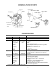
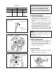
NOMENCLATURE OF PARTS Top guard Gear housing Drive shaft assembly Muffler Spark plug Ignition switch Throttle trigger Shield Grip Choke knob Air cleaner Fuel tank Starter handle cover Shoulder harness TECHNICAL DATA SRM-3800 TYPE1-E Dimension L×W×H Masses Engine cm (inch) kg (lbs) Type Displacement Max revolution Carburetor Ignition mL (cu.inch) r/min Spark plug Starter Clutch Fuel Mixing ratio Tank capacity Drive shaft assembly 181.5 × 72 × 46 (71.5 × 28.4 × 18.1) 8.0 (17.
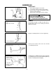
ASSEMBLING DRIVE SHAFT • • • Bolts • Stand engine uprignt on a level floor. Loosen bolts at drive shaft end of the engine. Fit drive shaft assembly ensuring that the drive shaft is correctly engaged. Tignten bolts to fasten drive shaft assembly. WARNING DANGER NEVER START ENGINE WITHOUT DRIVESHAFT ASSEMBLY INSTALLED. THIS COULD RESULT IN SERIOUS INJURY. 1. Right hand grip assembly 2. Slot 3.
1. 2. 3. 4. Loosen 4 right handle assembling bolts and insert right hand U-handle into right handle assembling bracket. (toward direction of arrow ) Right handle assembling bolt Right handle assembling bracket Right hand U-handle 1 To engine 2 Fix the right hand U-handle by tightening 4 right handle assembling bolts lightly. 3 4 Adjust each inclination of right and left handles to adequate position (easy to operate) and tighten firmly handle assembling bolt (8 mm) and 4 right handle assembling bolts.
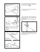
THROTTLE CABLE Nut (A) Swivel Nut (B) The engine is delivered with throttle cable (engine side) separated, assemble the cable to carburetor as follows. • Remove the cover. • Remove nut (A) and one washer from throttle cable. • Insert throttle cable througn the hole of bracket as shown. • Replace washer and nut (A) finger tignt, and attach the inner cable to swivel on throttle lever ensuring that the nipple fits into socket provided on one side of slot. • Tighten nut (A) to secure in this position.
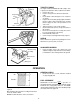
Fuel mix chart (50 : 1) US GAS GAL. 1 2 5 OIL FL.OZ. 2.6 5.1 12.8 IMPORTANT Stored fuel ages. Do not mix more fuel than you expect to use in thirty (30) days, ninety (90) days when a fuel stabilizer is added. Stored two-stroke fuel may separata. ALWAYS shake fuel container thoroughly before each use. METRIC GAS OIL L mL 4 80 8 160 20 400 STARTING COLD ENGINE • • • Throttle trigger Ignition switch • • Throttle control lockout Slide switch to START/RUN position as shown.
OPERATING THE TRIMMER • • • • • Adjust handle to a convenient position for cutting as instructed on page 5. Allow the engine to warm up at a fast idle for a few minutes. Increase engine speed as necessary. When mowing shrubs, weeds, or grass, swing the cutter head from right to left as you move forward. Avoid striking any obstruction such as rocks, stones or tree stumps which can damage the cutter head . Do not cut into the ground.
ECHO 2-LINE MANUAL TRIMMER HEAD (OPTION) WARNING DANGER GRASS/WEED TRIMMERS CAN THROW GRAVEL, STONE, WOOD CHIPS, GLASS, AND PLASTIC OR METAL OBJECTS. THE DEBRIS SHIELD BEHIND THE TRIMMER HEAD STOPS MUCH OF THE DEBRIS, BUT CANNOT PREVENT THE OPERATOR FROM BEING STRUCK BY SOME DEBRIS. READ THE RULES FOR SAFE OPERATION IN THE OPERATOR’S MANUAL THAT YOU RECEIVED WITH YOUR ECHO TRIMMER. AISO, FOLLOW AII INSTRUCTIONS IN THIS INSTRUCTION SHEET. 1. Read the Operator’s Manual carefully.
INSTALLATION OF NYLON LINE HEAD (OPTION) Locking tool Upper fixing plate Cutting head Set the nylon line head to the drive shaft and tighten by turning as shown. TIGHTEN OPERATING INSTRUCTIONS nylon line 1. Always use the end of the line for cutting. Forcing the cutter head too close to the work will result in reduced efficiency and broken line. 2. Maintain the line at the recommended length of 12.5 to 15 cm ( 5 to 6 inch ).
TRIMMING The nylon line will allow you to trim along walls and fence lines. Always try to trim from right to left, walking behind the unit and parallel to the wall or fence, thus deflecting debris away from the operator. EDGING 1. The nylon line is intended only to cut grass and should not be used to cut a normal edging trench along stone or concrete driveway etc. 2. Tilt the unit vertically as illsutrated and use only the line tip to remove unwanted growth.
STEEL BLADE OPERATIONS Your ECHO Trimmer/Brushcutter is designed for fast, efficient weed and brush control in areas which are otherwise inaccessable to power equipment. Standard configuration includes a handle bar and nylon line head for light trimming and weed clearing. Two special steel blades are available as options and recommended for use in extended heavy weed and brush clearing operations : 1.Blade: weed and grass 8 tooth 20 cm (8 inch) diameter 2.
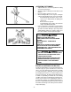
SHOULDER HARNESS • • PULL • Install the harness over the both shoulders and adjust shoulder straps so that the quick release latch rests low on the right hand side. Attach the trimmer/brushcutter to the harness by means of the quick release latch. Make some practice sweeps as with a scythe and readjust the harness as necessary for comfort and to maintain the cutter parallel to the ground.
INSTALLING THE BLADE 1. The installation of the 8 tooth weed/grass blade (option) and the 80 tooth brush is exactly the same. Brush Blade (80 tooth) Weed/Grass Blade (8 tooth) 2. Rotate the drive shaft until the holes in the upper fixing plate and the gear box are aligned. Insert the locking tool. Upper fixing plate Locking tool 3. Remove the nylon line line head, if fitted, by turning in a clockwise direction. 4. Install the blade ensuring that it is centered correctly on the fixing plate. 5.
HEAVY WEED CUTTING • • Install the 8 tooth 20 cm (8 inch) blade. (option) Observing all precautions as listed in this manual, start the engine and using full throttle, swing the blade in an arc as you move forward slowly. The cutter rotates counterclockwise and the debris will be pushed backwards so the work area will always be visible. BRUSHCUTTING • • Install the 80 tooth blade. Proceed exactly as for weed and grass cutting. SMALL TREES • • • • The unit will effectively cut small trees up to 7.
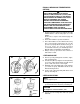
MAINTENANCE AND CARE - ALWAYS KEEP THE UNIT CLEAN AIR FILTER • Air filter Cover Clean before using the unit. Remove the cover. (for air filter and carburetor) Take off the air filter. Brush off dust lightly or wash it in suitable cleaning fluid. When you wash it in a solvent, dry it completely before putting back in place. FUEL STRAINER • Check periodically. Do not allow dust to enter into fuel tank. Clogged strainer will cause difficulty in starting engine or abnormalities in engine performances.
SPARK PLUG • • • • Check periodically. Standard spark plug gap is 0.6 - 0.7 mm (0.024 - 0.028 in). Replace if either electrode is worn or if the insulator is fouled by oil or other deposits. TORQUE = 14.2 - 15.2 N⋅⋅ m (125 - 135 in.lb) 0.6 - 0.7mm (.024 - .028 in.) CAUTION Do not over torque. GEAR HOUSING • • Gear housing Remove the bolt every 50 hours and check. Replenish as necessary, but do not overfill. Shell delpena or good quality lithium multi grease is recommendable.
6. Accelerate to full throttle for 2 - 3 seconds to clear any excess fuel in the engine, then return to idle. Accelerate engine to full throttle to check for smooth transition from idle to high speed. If engine hesitates turn “L” needle CCW 1/8 turn and repeat acceleration. Continue adjustment until smooth acceleration results. 7. Check idle speed and reset if necessary as described in item 5. CAUTION When strarting, idling adjustment speed should be adjusted not to rotate the cutting attachment.
TROUBLE SHOOTING Poor performance of the engine and/or trimming mechanism can normally be prevented by carefully following instructions. Poor performances can easily be corrected even by a beginner. When the engine does not function properly check the following three (3) points first.
Table 2 Machine does not trim properly Engine speed insufficient Engine overheated Use fuel with correct mixing ratio. Never use gasoline of poor quality. Spark plug defective (burnt) Replace. As cooling fins clogged, air does not pass well Clean fins. Excessive deposits in combustion chamber Disassemble and remove carbon. Plug damaged or fouled Replace or clean. Combustion poor due to defective wiring Check wiring. High-speed needle setting incorrect Readjust.