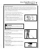
Grass Trimmer/Brush Cutter Operator's Manual MODEL SRM - 410U WARNING Read rules for safe operation and instructions carefully. ECHO provides an Operator's Manual and a Safety Manual. Both must be read and understood for proper and safe operation.
Introduction Welcome to the ECHO family. This ECHO product was designed and manufactured to provide long life and on-the-job dependability. Read and understand this manual and the SAFETY MANUAL you found in the same package. You will find both easy to use and full of helpful operating tips and SAFETY messages. the operator's manual Read and understand this manual before operation. Keep it in a safe place for future reference.
Grass Trimmer/Brush Cutter Operator's Manual 3 Safety manual safety symbols and important information Throughout this manual and on the product itself, you will find safety alerts and helpful, informational messages preceded by symbols or key words. The following is an explanation of those symbols and key words and what they mean to you. Circle and slash symbol DANGER This symbol means the specific action shown is prohibited. Ignoring these prohibitions can result in serious or fatal injury.
Physical Condition Your judgment and physical dexterity may not be good: • if you are tired or sick, • if you are taking medication, • if you have taken alcohol or drugs. Operate unit only if you are physically and mentally well. Eye Protection Wear eye protection that meets ANSI Z87.1 or CE requirements whenever you operate the unit. Hand Protection Wear no-slip, heavy-duty work gloves to improve your grip on the handle. Gloves also reduce the transmission of machine vibration to your hands.
Grass Trimmer/Brush Cutter Operator's Manual Repetitive Stress Injuries 5 It is believed that overusing the muscles and tendons of the fingers, hands, arms, and shoulders may cause soreness, swelling, numbness, weakness, and extreme pain in those areas. Certain repetitive hand activities may put you at a high risk for developing a Repetitive Stress Injury (RSI).
equipment WARNING Use only ECHO approved attachments. Serious injury may result from the use of a non-approved attachment combination. ECHO, INC. will not be responsible for the failure of cutting devices, attachments or accessories which have not been tested and approved by ECHO. Read and comply with all safety instructions listed in this manual and safety manual. • Check unit for loose/missing nuts, bolts, and screws. Tighten and/or replace as needed.
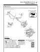
Grass Trimmer/Brush Cutter Operator's Manual 7 Description Locate these safety decals on your unit. Make sure the decals are legible and that you understand and follow the instructions on them. If a decal cannot be read, a new one can be ordered from your ECHO dealer. See PARTS ORDERING instructions for specific information.
POWER HEAD - Includes the Engine, Clutch, Fuel System, Ignition System and Recoil Starter. THROTTLE TRIGGER LOCKOUT - This lever must be held during starting. Operation of the throttle trigger is prevented unless throttle trigger lockout lever is engaged. 3. STOP SWITCH - "SLIDE SWITCH" mounted on top of the Throttle Trigger Housing. Move switch FORWARD to RUN, BACK to STOP. 4. THROTTLE TRIGGER - Controls engine speed. Spring loaded to return to idle when released.
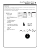
Grass Trimmer/Brush Cutter Operator's Manual 9 Contents The ECHO product you purchased has been factory pre-assembled for your convenience. Due to packaging restrictions, shield installation and other assembly may be necessary. After opening the carton, check for damage. Immediately notify your retailer or ECHO Dealer of damaged or missing parts. Use the contents list to check for missing parts.
Assembly drive shaft/power head Tools Required: 4 mm Hex Wrench Parts Required: Power Head, Drive Shaft Assembly 1. 2. 3. 4. Stand power head upright on a level surface. Loosen the drive shaft clamp bolt (A) at engine drive shaft clamp, and remove drive shaft locating bolt (B). Remove protective plastic cap from end of drive shaft assembly. Carefully fit driveshaft assembly to engine making sure that inner drive shaft engages clutch mount.
Grass Trimmer/Brush Cutter Operator's Manual 1. Align hole in upper plate (D) with notch in gear housing (E), and insert locking tool to prevent splined shaft from turning. Arrow on gear housing flange points to notch location. 2. Remove split pin (F), L.H. blade nut (G), lower plate (H), and upper plate (D) from PTO shaft. Turn blade nut clockwise to remove. 3. Remove locking tool. E D H 4.
u-handle installation Tools Required: 17 & 19 mm wrench, 4 mm hex wrench A Parts Required: U-Handle, Clamp w/screws, 8 mm x 55 mm hex bolt, 8 mm flat washer 1. 2. Remove assembling bolt (A) from right hand grip. Install right hand grip (B) onto right hand U-handle (C) until bolt hole in Uhandle is visible through bolt hole in bottom of grip. Grip should not rotate on handle. B Install assembling bolt to secure grip onto U-handle. C 3.
Grass Trimmer/Brush Cutter Operator's Manual 6. Secure the right hand U-handle by tightening 4 right handle assembling bolts (H) loosely. H E 7. Adjust handles for comfortable operation and tighten handle assembling bolt (E) and 4 right handle assembling bolts (H). 8. Route throttle linkage and ignition lead assembly along shaft and clip as shown. balance and adjust unit 1. Loosen harness clamp screw. 2. Put on harness and attach unit to harness. 3.
optional nylon head installation Tools Required: Locking Tool Parts Required: Nylon Line Head. 1. Align hole in upper plate with notch in gear housing, and insert locking tool to prevent splined shaft from turning. 2. Thread line head onto PTO shaft by turning it counter-clockwise until head is tight against upper plate. 3. Remove locking tool. • Read the Operator’s Manual carefully. Be thoroughly familiar with the controls and proper use of the trimmer.
Grass Trimmer/Brush Cutter Operator's Manual 15 2.REPLACING SPOOL NOTE Keep line tight on spool. A. Snap spool into housing while pulling line through eyelets with about 15 cm (6 in) extending out. Locking tool Upper fixing plate Cutting head CAUTION Knob tightens counterclockwise, “left”. B. Fasten spool to housing with shaft bolt, spring, and knob. TIGHTEN operating instructions nylon line 1. 2. 3. 4. Always use the end of the line for cutting.
Operation WARNING Moving parts can amputate fingers or cause severe injuries. Keep hands, clothing and loose objects away from all openings. Always stop engine, disconnect spark plug, and make sure all moving parts have come to a complete stop before removing obstructions, clearing debris, or servicing unit. WARNING Engine exhaust IS HOT, and contains Carbon Monoxide (CO), a poison gas. Breathing CO can cause unconsciousness, serious injury, or death. Exhaust can cause serious burns.
Grass Trimmer/Brush Cutter Operator's Manual Plastic/Nylon Grass/Weed Blades may be used where ever the nylon line head is used. DO NOT use this blade for heavy weeds or brush! 8 Tooth Weed/Grass Blade is designed for grass, garden debris and thick weeds. DO NOT use this blade for brush or heavy woody growth, 19 mm (3/4 in.) diameter or larger. 80 Tooth Brush Blade is designed for cutting brush and woody growth up to 13mm (3 in.) diameter.
fuel NOTICE: Use of unmixed, improperly mixed, or fuel older than 90 days, (stale fuel), may cause hard starting, poor performance, or severe engine damage and void the product warranty. Read and follow instructions in the Storage section of this manual. WARNING Alternative fuels, such as E-20 (20% ethanol), E-85 (85% ethanol) or any fuels not meeting ECHO requirements are NOT approved for use in ECHO 2-stroke gasoline engines.
Grass Trimmer/Brush Cutter Operator's Manual Mixing Instructions 1. Fill an approved fuel container with half of the required amount of gasoline. 2. Add the proper amount of 2-stroke oil to gasoline. 3. Close container and shake to mix oil with gasoline. 4. Add remaining gasoline, close fuel container, and remix. IMPORTANT Spilled fuel is a leading cause of hydrocarbon emissions. Some states may require the use of automatic fuel shut-off containers to reduce fuel spillage.
starting cold engine A WARNING When engine is started, confirm that there is not any abnormal vibration or sound. If there is abnormal vibration or sound, ask your DEALER to repair. After refueling tighten fuel cap firmly and check for leakage. In case of fuel leakage repair before starting operation since there is a danger of fire. 1. Stop Switch Move stop switch button (A) forward away from the STOP position. 2. Choke Move choke lever (B) to Cold Start Position ( B ). 3.
Grass Trimmer/Brush Cutter Operator's Manual starting warm engine 1. Press the decompression device (E). E A 2. Stop Switch Move stop switch button (A) forward away from the STOP position. 3. Purge Bulb Pump purge bulb (C) until fuel is visible in the "Clear" fuel return line. D C 4. Recoil Starter Lay the unit on a flat area and keep movable attachment parts clear of all obstacles. Hold unit firmly and rapidly pull the recoil starter handle (D) until the engine fires.
Maintenance WARNING Moving parts can amputate fingers or cause severe injuries. Keep hands, clothing and loose objects away from all openings. Always stop engine, disconnect spark plug, and make sure all moving parts have come to a complete stop before removing obstructions, clearing debris, or servicing unit. Allow unit to cool before performing service. Wear gloves to protect hands from sharp edges and hot surfaces. Your ECHO trimmer is designed to provide many hours of trouble free service.
Grass Trimmer/Brush Cutter Operator's Manual air filter Level 1. Tools required: 25 - 50mm (1 - 2 in.) cleaning brush Parts required: REPOWERTM Tune-Up Kit NOTE Always brush dirt and debris away from air cleaner area prior to cleaning air filter. 1. Brush dirt off air cleaner area. Keep dirt away from engine and air intake grid. 2. Remove air filter cover (A). Brush dirt from inside cover and away from edges of air filter. 3. Check air filter seal for tight fit with air filter case. 4.
fuel filter Level 1. Tools required: 200- 250 mm (8 - 10 in.) length of wire with one end bent into a hook, clean rag, funnel, and an approved fuel container. Parts required: REPOWERTM Tune-Up Kit DANGER Fuel is VERY flammable. Use extreme care when mixing, storing or handling. 1. Use a clean rag to remove loose dirt from around fuel cap and empty fuel tank. 2. Use the “fuel line hook” to pull the fuel line and filter from the tank. 3.
Grass Trimmer/Brush Cutter Operator's Manual cooling system Level 2. Tools required: Air compressor and safety nozzle, or: 4 mm Hex wrench, 25 - 50 mm (1 - 2 in.) cleaning brush. Parts Required: None. IMPORTANT To maintain proper engine operating temperatures, cooling air must pass freely through the cylinder fin area. This flow of air carries combustion heat away from the engine.
Exhaust Port Cleaning Level 2. Tools required: 4 & 5 mm Hex Wrench, Wood or plastic scraper Parts Required: As needed: Heat Shield 1. Remove spark plug lead from spark plug, and remove muffler cover (2 screws). 2. Place piston at top dead center. Remove muffler (A) and heat shield (B). 3. Use a wood or plastic scraping tool to clean deposits from cylinder exhaust port. IMPORTANT Never use a metal tool to scrape carbon from the exhaust port.
Grass Trimmer/Brush Cutter Operator's Manual 27 CARBURETOR ADJUSTMENT Engine Break-In New engines must be operated a minimum of two tanks of fuel before carburetor adjustments can be made. During the break-in period your engine performance will increase and exhaust emissions will stabilize. Idle speed can be adjusted as required.
lubrication Level 1. Tools Required: 8 & 13 mm Open End Wrench, Screwdriver, Clean Rag. Parts Required: POWER BLENDXTM 8 oz. (P/N 91014) or Lithium Base Grease. Gear Housing 1. Clean all loose debris from gear box. 2. Remove plug (A) and check level of grease. Grease should fill gear case to bottom of grease plug hole. 3. Add grease if necessary using manual grease gun or squeeze-type tube. Do not use high pressure grease gun. DO NOT over-fill.
Grass Trimmer/Brush Cutter Operator's Manual sharpening metal blades Three styles of metal blades are approved for use on the ECHO Brush Cutter. The 8-tooth blade can be sharpened during normal maintenance. The clearing blade and 80 tooth blade require professional service. Before sharpening, CLOSELY inspect blade for cracks (look at the bottom of each tooth and the center mounting hole closely), missing teeth and bending. If ANY of these problems are discovered, replace the blade.
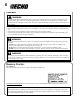
Troubleshooting ENGINE PROBLEM TROUBLESHOOTING CHART Problem C h eck Fuel at carburetor Fuel at cylinder Engine cranks starts hard/ doesn't start Engine runs, but dies or does not accelerate properly Engine does not crank Status C au se No fuel at carburetor Fuel strainer clogged Fuel line clogged Carburetor Remedy Clean or replace Clean or replace See your Echo dealer No fuel at cylinder Carburetor See your Echo dealer Muffler wet with fuel Fuel Mixture too rich Open choke Clean/replace ai
Grass Trimmer/Brush Cutter Operator's Manual 31 Storage warning During operation the muffler or catalytic muffler and surrounding cover become hot. Always keep exhaust area clear of flammable debris during transportation or when storing, otherwise serious property damage or personal injury may result. Long Term Storage (over 30 days) Do not store your unit for a prolonged period of time (30 days or longer) without performing protective storage maintenance which includes the following: 1.
Specifications MODEL ���������������������������������������������������� SRM-410U Length ������������������������������������������������������� 1860 mm (73.2 in.) Width �������������������������������������������������������� 630 mm (24.8 in.) Height ������������������������������������������������������� 470 mm (18.5 in.) Weight (dry) w/Cutter Head ������������������������������ 8.3 kg (18.3 lb.
Grass Trimmer/Brush Cutter Operator's Manual notes 33
notes
Grass Trimmer/Brush Cutter Operator's Manual notes 35
7-2 SUEHIROCHO 1-CHOME, OHME, TOKYO, 198-8711, JAPAN PHONE: 81-428-32-6118 FAX: 81-428-32-6145 ECHO, INCORPORATED 400 Oakwood Road Lake Zurich, IL 60047-1564 GB © 2009 S05403001001/S05403999999