
User manual


6
3.2. Mains connection
The DPA amplifiers are fed with alternate currents, depending on the country, of 110-120, 220-240V
47-63Hz. (see characteristics in the back of the unit) consuming:
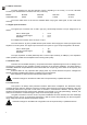
MODEL DPA600 DPA1000 DPA1400 DPA2000
CONSUMPTION 830VA 1250VA 1720VA 3115VA
The mains cables must not be near the shielded cables carrying the audio signal, as this could cause
humming.
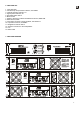
3.3. Signal input connections
The signal input connectors are of XLR-3 type (10), electronically balanced. The pin assignment is as
follows:
HOT or direct signal > Pin 2
COLD or inverted signal > Pin 3
GROUND > Pin 1
For unbalanced connection short-circuit pin 3 to pin 1.
The “STK OUTPUT” (9) are in parallel with the inputs and are used to supply the same input signal to other
amplifiers or sound systems. This signal output connectors are of jack 1/4" type. The pin assignment is as follows:
HOT or direct signal > Tip
COLD or inverted signal > Ring
GROUND > Body
The input impedance is 22K (balanced) with a nominal input sensitivity of 0dBV(1V). This impedance
makes possible to parallel several amplifiers without loosing audio quality.
3.4. Subsonic filter
This filter cuts off inaudible frequency components which when amplified suppose a risk of damage to the
low frequency speakers as they generate excessive excursions of the woofer's diaphragm. The DPAs feature a
switchable, Butterworth shaped Subsonic Filter located inside the unit (see fig.) with a 25Hz cut-off frequency and
18dB/oct slope.
Subsonic filters are very important when playing back vinyl records because the phono cartridges are
specially sensitive to feedback and acoustic coupling at very low frequencies.
DPA amplifiers are delivered with switched ON Subsonic Filter.
CAUTION: Changes on the Subsonic Filter have to be performed by a qualified technician.
3.5. Limiter circuit
This system is an always active protection inside the DPA series of amplifiers. The ANTICLIP circuitry
constantly analyses harmonic distortion caused by excessive signal excursion at the power amplifier's output and
automatically reduces the input level in order never to exceed 1% total harmonic distortion. The DPA range of
amplifiers are delivered with the anticlip system adjusted at a threshold of 1% THD (hard limiting). However, this
value can be switched to a softer limiting (5% THD) via an internal jumper (see fig.).
The great convenience of such a circuit in any kind of installation has to be remarked: The clear advantage
of a limiting system in front of conventional compressors is that the former does practically not alter the dynamic
range, acting only when the distortion threshold is reached.
CAUTION: Changes on the ANTICLIP configuration have to be performed by a qualified technician.