
User manual


7
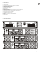
3.6. Output connections
The OUTPUT section on the rear panel features Speakon connectors (12).
Whenever you need to operate the amplifier in BRIDGED mode (mono or bridged), you must set the
“STEREO BRIDGED" Switch (11) to BRIDGED. The input signal is taken from the CHANNEL 1 connector and the
signal output to the loudspeaker is on pins 2+ and 2- of the Speakon connector “CH1”. The same contacts (2+ and 2-)
of the Speakon connector of CH2 also carry the bridged signal in order to facilitate the parallel connection of
loudspeakers.
ATTENTION: Terminals 1+, 1- must only be used in STEREO operation and terminals 2+, 2- in BRIDGED
operation. Other combinations would lead to poor output quality.
Please make sure that the resulting impedance of your installation, when the amplifier is operating in BRIDGE
mode, is never lower than 4 Ohm (8 Ohm recommended).
The connection cable that joins the amplifiers outputs and the loudspeakers must be of good quality,
sufficient section and as short as possible. This is most important when the distances to cover are long ones i.e. up
to 10 meters it is recommended to use a section not inferior to 2.5mm
2
and for superior distances 4mm
2
.
4. OPERATION AND USAGE
4.1. Start up
Pushing the POWER (5) button lights up the integrated pilot light and both red CLIP PROT (2) LEDs during
the approximately 10 seconds needed to stabilize all voltages. The CLIP PROT LEDs will then turn off meaning
that the amplifier is now operative.
In a complete audio installation, it is important to start up the equipment in the following sequence: sound
sources, mixer, equalizers, active filters and finally power amplifiers. To turn them off the sequence should follow
an inverse pattern.
4.2. Input attenuators
This consists of rotative potentiometers, situated on the front panel (1).
These attenuators enable the connection of different types of mixing tables, independent regulation level
and loudspeaker connections that allow an inferior power level that the level already supplied by the power
amplifier at its maximum power, with no danger of damaging, by careless handling, the volume of the pre-amplified
mixer.
Inside the device's packaging you will find a little plastic bag containing 2 transparent caps which protect the
input attenuation settings from unwanted manipulation. These caps are transparent in order to let you visualize the
current settings.
Once inserted, they cannot be removed with bare fingers, for this purpose, a small screwdriver is needed.
4.3. Indicators
The DPA amplifiers are equipped with a simple but efficient combined indicators system.
Indicator CLIP/PROT (2) function as PROTECTION indicator.
They point to the lack of signal at the speaker outputs. These indicators may light up due to following reasons:
1. From the moment the machine is switched on, until stand by period finalise that is necessary for the
stability of the internal tensions of the power amplifier.
2. Because the amplifier output has short circuited.
3. If the amplifier is giving a continuous voltage or is of very low frequency, this could damage the
loudspeakers.
In any case, should these indicators permanently light up, it is a sign of malfunctioning and its cause should
be investigated.