USER MANUAL MANUAL DE INSTRUCCIONES NOTICE D'UTILISATION BEDIENUNGSANLEITUNG MPAGE1 PAGING STATION
INSTRUCTION MANUAL 1. IMPORTANT NOTE 1.1. Precautions 04 04 2. INTRODUCTION 04 3. INSTALLATION and CONNECTION 05 4. OPERATION 06 5. FUNCTION LIST 07 6. FUNCTION DIAGRAM 07 7. TECHNICAL CHARACTERISTICS 23 All numbers subject to variation due to production tolerances. ECLER SA reserves the right to make changes or improvements in manufacturing or design which may affect specifications.
1. IMPORTANT NOTE Congratulations! You are the owner of a carefully designed and manufactured product. We would like to thank you for choosing our MPAGE1 paging station. For the maximum effectiveness of the paging station, it is VERY IMPORTANT that you read this User's Guide carefully and follow the recommendations contained herein. In order to guarantee the optimum operation of this unit, we strongly recommend that its maintenance be carried out by our Authorised Technical Services. 1.1.
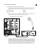
3. INSTALLATION and CONNECTION Installing a MPAGE1 unit consists of the following steps: 1. Installation of audio wiring: cable balancing between the MICRO (3) connection of the MPAGE1 and the audio input of the receiving equipment (mixer, audio matrix, etc.): Live or direct signal Cold or inverted signal Ground > > > Terminal + Terminal Terminal A The audio cable also delivers the phantom power required for the MPAGE1 unit to operate and which must be supplied remotely by the receiver.
Note: the TRIGGER control signal is not a power-free contact closure; rather, it operates thanks to a circuit based on MOSFET devices. For more information, consult the technical features of the equipment. 3. Adjust the microphone level of the receiver equipment The console (2) microphone is a non-extractable electret cardioid type mounted on a flexo. It is supplied with an "anti-pop" foam windshield. 4.
5. FUNCTION LIST 1. PAGE key 2. Goose-neck microphone 3. Euroblock connector, MICRO 4. Euroblock connector, TRIGGER 6.
MANUAL DE INSTRUCCIONES 1. NOTA IMPORTANTE 1.1. Precauciones 09 09 2. INTRODUCCIÓN 09 3. INSTALACIÓN y CONEXIONADO 10 4. FUNCIONAMIENTO 11 5. LISTA DE FUNCIONES 12 6. DIAGRAMA DE FUNCIONES 12 7. CARACTERÍSTICAS TÉCNICAS 23 Todos los datos están sujetos a variación debida a tolerancias de producción. ECLER S.A. se reserva el derecho de realizar cambios o mejoras en la fabricación o diseño que pudieran afectar las especificaciones.
1. NOTA IMPORTANTE ¡Enhorabuena!. Vd. posee el resultado de un cuidadoso diseño y una esmerada fabricación. Agradecemos su confianza por haber elegido nuestra estación de avisos MPAGE1. Para conseguir la máxima operatividad y rendimiento del aparato, antes de su conexión, es MUY IMPORTANTE leer detenidamente y tener muy presentes las consideraciones que se especifican en este manual.
3. INSTALACIÓN y CONEXIONADO La instalación de una unidad MPAGE1 consta de los siguientes pasos: 1. Instalación del cableado de audio: cable balanceado entre el conector MICRO (3) de la MPAGE1 y la entrada de audio del equipo receptor (mezclador, matriz de audio, etc.
Nota: la señal de control TRIGGER no es un cierre de contacto libre de potencial, sino que actúa gracias a un circuito basado en dispositivos MOSFET. Para más información, vea las características técnicas del equipo. 3. Ajuste del nivel de micrófono en el equipo receptor El micrófono de la consola (2) es del tipo electret cardioide, montado en un flexo y no extraíble. Se suministra con una cubierta de espuma “anti-pop“. 4.
5. LISTA DE FUNCIONES 1. Pulsador PAGE 2. Micrófono de cuello de cisne 3. Conector Euroblock, MICRO 4. Conector Euroblock, TRIGGER 6.
NOTICE D’UTILISATION 1. NOTE IMPORTANTE 1.1. Précautions 14 14 2. INTRODUCTION 14 3. INSTALLATION et CONNEXIONS 15 4. FONCTIONNEMENT 16 5. LISTE DE FONCTIONS 17 6. SCHÉMA DE FONCTIONS 17 7. CARACTÉRISTIQUES TECHNIQUES 23 Toutes les valeurs mentionnées dans ce document sont susceptibles d’être modifiées en raison des tolérances de production.
1. NOTE IMPORTANTE Félicitations ! Vous avez entre les mains le résultat d'une conception et d'une fabrication soignées. Nous vous remercions de la confiance que vous nous avez témoignée en choisissant notre console d'annonces MPAGE1. Pour en tirer le meilleur rendement et un fonctionnement maximal, il est TRÈS IMPORTANT de lire attentivement et de respecter les indications de ce manuel avant toute connexion.
3. INSTALLATION et CONNEXIONS L'installation d'une unité MPAGE1 doit suivre les étapes suivantes : 1. Installation du câblage audio : câble symétrique entre le connecteur MICRO (3) de la console MPAGE1 et l'entrée audio de l'appareil récepteur (mélangeur, matrice audio, etc.
Remarque : le signal de contrôle TRIGGER n'est pas une fermeture de contact libre de potentiel ; il agit grâce à un circuit basé sur des dispositifs MOSFET. Pour plus d'informations, consulter les caractéristiques techniques de l'appareil. 3. Réglage du niveau du microphone sur l'appareil récepteur Le microphone de la console (2) est du type cardioïde à électret, monté sur flexible et non démontable. Il est fourni avec une bonnette en mousse « anti-plosive ». 4.
5. LISTE DE FONCTIONS 1. Bouton de commande PAGE 2. Microphone à col de cygne 3. Connecteur Euroblock, MICRO 4. Connecteur Euroblock, TRIGGER 6.
BEDIENUNGSANLEITUNG 1. WICHTIGER HINWEIS 1.1. Vorsichtsmaßnahmen 19 19 2. EINLEITUNG 19 3. INSTALLATION und ANSCHLUSS 20 4. BETRIEB 21 5. LISTE DER FUNKTIONEN 22 6. FUNKTIONSDIAGRAMM 22 7. TECHNISCHE DATEN 23 Alle angegebenen Werte unterliegen gewissen Schwankungen infolge Produktionstoleranzen. ECLER S.A. behält sich das Recht zu Änderungen oder Weiterentwicklungen in Produktion oder Design vor, die Abweichungen der technischen Daten zur Folge haben können.
1. WICHTIGER HINWEIS Glückwunsch! Was Sie besitzen, ist das Resultat einer detaillierten Konstruktion und sorgfältigen Herstellung. Wir bedanken uns für das Vertrauen, das Sie mit der Wahl unserer Sprechstelle MPAGE1 in uns gesetzt haben. Um eine optimale Handhabung und die maximale Leistung des Geräts zu erreichen, ist es SEHR WICHTIG, vor dem Anschluss die in dieser Anleitung enthaltenen Hinweise aufmerksam durchzulesen und zu berücksichtigen.
3. INSTALLATION und ANSCHLUSS Für die Installation einer MPAGE1 sind folgende Schritte notwendig: 1. Installation des Audiokabels: symmetrisches Kabel zwischen dem Anschluss MICRO (3) der MPAGE1 und dem Audioeingang des Empfangsgeräts (Mischpult, Audiomatrix usw.): Life bzw. direktes Signal Kalt bzw.
Hinweis: Beim Steuersignal TRIGGER handelt es sich nicht um einen potenzialfreien Kontaktabschluss, die Wirkung beruht auf einem Stromkreis von MOSFET-Geräten. Weitere Informationen erhalten Sie in den technischen Daten des Geräts. 3. Einstellung des Mikrofonpegels im Empfangsgerät Das Mikrofon der Konsole (2) ist ein electret Kardioid-Mikrofon, das an einem flexiblen Arm montiert und nicht abnehmbar ist. Es wird mit einer ”anti-pop” Schaumstoff-Abdeckung geliefert. 4.
5. LISTE DER FUNKTIONEN 1. Taste PAGE 2. Schwanenhalsmikrofon 3. Anschluss Euroblock, MICRO 4. Anschluss Euroblock, TRIGGER 6.
7. TECHNICAL CHARACTERISTICS 7. CARACTERÍSTICAS TÉCNICAS 7. CARACTÉRISTIQUES TECHNIQUES 7. TECHNISCHE DATEN Microphone type Non removable gooseneck condenser microphone Polar pattern Unidirectional Microphone frequency response 50Hz – 18KHz (-10dB) Output level -20dBV @ 104dB SPL Page mute 80dB typ. Audio output Balanced, detachable 3 pole screw terminal Maximum audio cable length Twisted pair 5m Shielded 60m Control output Open drain N channel mosfet N.C. Control rating Max.
ECLER Laboratorio de electro-acústica S.A. Motors 166-168, 08038 Barcelona, Spain INTERNET http://www.ecler.com e-mail: info@ecler.es 50.0231.01.