INSTRUCTION MANUAL MANUAL DE INSTRUCCIONES NOTICE D’EMPLOI BEDIENUNGSANLEITUNG
INSTRUCTION MANUAL 1. IMPORTANT REMARK 04 2. WARNINGS 04 3. INTRODUCTION 04 4. MODELS AND CHARACTERISTICS 05 5. QUICK START 06 6. USE 07 7. OTHER CONSIDERATIONS 09 8. FUNCTION DIAGRAM 10 9. APPLICATION AND MOUNTING EXAMPLE DIAGRAMS 35 10. TECHNICAL CHARACTERISTICS 37 11. BLOCK DIAGRAM 38 All numbers subject to variation due to production tolerances. ECLER, S.A. reserves the right to make changes or improvements in manufacturing or design which may affect specifications.
1. IMPORTANT REMARK Congratulations. You are now the owner of the result of careful design and exquisite manufacture. Thank you for having chosen our powered loudspeaker cabinet VERSO P. In order to get the optimum operation and efficiency from this unit, it is VERY IMPORTANT - before you plug anything - to read this manual very carefully and bear in mind all considerations specified within it. We strongly recommend that its maintenance be carried out by our Authorised Technical services. 2.
4. MODELS AND CHARACTERISTICS The VERSO P series is formed by thee models, all two-way and self-powered separately: VERSO 8P (200W RMS): • Low-medium frequency: 8” bass speaker (woofer). • High frequency: 34mm motor. VERSO 10P (300W RMS): • Low-medium frequency: 10” bass speaker (woofer). • High frequency: 34 mm motor. VERSO 12P (450W RMS): • Low-medium frequency: 12” bass speaker (woofer). • High frequency: 44 mm motor.
5. QUICK START 1. Location: Choose a site from where the audience area can be covered in which there are very few obstacles between audience and speaker. The higher the speaker is placed, the greater and better the audience coverage will be. Since this is a self-amplifying box, it requires direct connection to a power socket. This must be taken into consideration. 2. Connecting to the mains: Read the WARNINGS paragraph in section 2. Check that the red switch is at “0”.
6. USE 1. Location and installation: The following general rules should be observed: • Stand or hang the cabinets on or from solid, firm surfaces. • There must be no obstacles between the acoustic box and the audience. High frequencies, unlike low ones, are extremely directive and any obstacle will cause an attenuation in its response. • For large audience areas, the higher the boxes are placed, the better the propagation of the sound over the distance.
4. Line Inputs: Their sensitivity is –10dBV (316mV). CD, DAT, MP3, DVD Audio players, keyboards, tape recorders, synthesisers, etc. and the signal from audio mixers can be connected to this type of input. If the signal source is not the balanced type, care must be taken to ensure that terminals 1 and 3 are short-circuited, terminal 2 being the active signal.
7. OTHER CONSIDERATIONS Ground loops: Ensure at all times that the signal sources reaching the unit and all the devices connected to its output do not have interconnected grounds, i.e., they should not be connected to ground through two or more different routes, since this could cause buzzing that would affect the sound reproduction quality. If cable shielding are connected to the chassis, they should be never interconnected, in order to avoid ground loops.
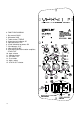
8. FUNCTION DIAGRAM 1. Bas control, BASS 2. Mid control, MID 3. Treble control, TREBLE 4. Signal present indicator, SP 5. Input attenuator, VOL 6. Visual indication for power, ON 7. Clip indicator, CLIP 8. Input, MICRO/LINE 9. XLR output connector to other amplifiers, STACK OUT 10. Input selector 11. Voltage change 12. On switch, O/I 13. Fuse holder 14. Mains socket 15.
MANUAL DE INSTRUCCIONES 1. NOTA IMPORTANTE 12 2. PRECAUCIONES 12 3. INTRODUCCIÓN 12 4. MODELOS Y CARACTERÍSTICAS 13 5. INICIO RÁPIDO 14 6. UTILIZACIÓN 15 7. OTRAS CONSIDERACIONES 17 8. DIAGRAMA DE FUNCIONES 18 9. DIAGRAMAS DE EJEMPLOS DE APLICACIÓN Y SUSPENSIÓN 35 10. CARACTERÍSTICAS TÉCNICAS 37 11. DIAGRAMA DE BLOQUES 38 Todos los datos están sujetos a variación debida a tolerancias de producción. ECLER S.A.
1. NOTA IMPORTANTE Enhorabuena. Vd. posee el resultado de un cuidado diseño y de una esmerada fabricación. Agradecemos su confianza por haber elegido nuestra caja acústica auto-amplificada de la serie VERSO P. Para conseguir su máxima operatividad y rendimiento es MUY IMPORTANTE, antes de su conexión, leer detenidamente y tener muy presentes las consideraciones que en este manual se especifican.
4. MODELOS Y CARACTERÍSTICAS La serie VERSO P está formada por tres modelos, todos de dos vías auto-amplificadas independientemente: VERSO 8P (200W RMS): • Vía de graves-medios: altavoz de graves (woofer) de 8”. • Vía de agudos: motor de 34mm. VERSO 10P (300W RMS): • Vía de graves-medios: altavoz de graves (woofer) de 10”. • Vía de agudos: motor de 34 mm. VERSO 12P (450W RMS): • Vía de graves-medios: altavoz de graves (woofer) de 12”. • Vía de agudos: motor de 44 mm.
5. INICIO RÁPIDO 1. Ubicación: Elija un lugar desde el que cubrir acústicamente el área de audiencia y en el que existan el menor número de obstáculos entre ésta y el altavoz. Contra más elevado coloque el altavoz, mayor y mejor será la cobertura de la audiencia. Al tratarse de un recinto auto-amplificado, éste requiere conexión directa a una toma de red y a las fuentes de sonido que se desee conectar. Prevea tal circunstancia. 2. Conexión a la red eléctrica: Lea las PRECAUCIONES del apartado 2.
6. UTILIZACIÓN 1. Ubicación y montaje: Como reglas generales se observarán las siguientes: • Colocar o suspender las cajas acústicas en superficies sólidas y firmes. • No debe existir ningún obstáculo entre los recintos acústicos y la audiencia. Las frecuencias agudas, a diferencia de las graves son extremadamente directivas y cualquier obstáculo supone una atenuación en su respuesta.
4. Entradas de Línea: Su sensibilidad es de –10dBV (316mV). Reproductores CD, DAT, MP3, DVD Audio, teclados, magnetófonos, sintonizadores, etc., así como la señal procedente de mezcladotes de audio, se conectarán a este tipo de entradas. Cuando la fuente de señal no sea del tipo balanceado se deberá tener la precaución de que los terminales 1 y 3 estén cortocircuitados y conectados a masa, siendo el terminal 2 el de la señal activa.
7. OTRAS CONSIDERACIONES Bucles de masa: Procure en todo momento que las fuentes de señal que lleguen a la unidad, así como todos los aparatos que estén conectados a su salida, no tengan las masas interconectadas, es decir, que nunca se conecten a masa por dos o más caminos distintos, ya que de esta manera se podrían producir zumbidos que llegarían incluso a interferir en la calidad de la reproducción sonora.
8. DIAGRAMA DE FUNCIONES 1. Control de frecuencias graves, BASS 2. Control de frecuencias medias, MID 3. Control de frecuencias agudas, TREBLE 4. Indicador luminoso de presencia de señal, SP 5. Atenuador de entrada, VOL 6. Indicador luminoso de puesta en marcha, ON 7. Indicador luminoso de recorte, CLIP 8. Entrada, MICRO/LINE 9. Conector XLR de salida para conexión en cadena, STACK OUT 10. Selector de entrada 11. Selector de tensión 12. Interruptor de puesta en marcha, O/I 13. Portafusibles 14.
NOTICE D’EMPLOI 1. NOTE IMPORTANTE 20 2. PRÉCAUTIONS 20 3. INTRODUCTION 20 4. MODÈLES ET CARACTÉRISTIQUES 21 5. DÉBUT RAPIDE 22 6. UTILISATION 23 7. AUTRES CONSIDÉRATIONS 25 8. SCHÉMA DE FONCTIONNEMENT 26 9. SCHEMAS D'EXEMPLES D'APPLICATION ET D'ACCROCHAGE 35 10. CARACTÉRISTIQUES TECHNIQUES 37 11. BLOCS DE DIAGRAMMES 38 Le contenu de ce manuel peut être amené à changer, du fait de tolérances de production. La société ECLER S.A.
1. NOTE IMPORTANTE Félicitations. Vous possédez le résultat d’une conception soignée et d’une fabrication de qualité. Nous vous remercions d’avoir choisi notre boîte acoustique auto amplifiée de la série VERSO P Pour obtenir un fonctionnement optimal et un rendement maximum de l'enceinte, il est TRES IMPORTANT, avant de procéder au raccordement de cette dernière, de lire attentivement ce manuel et les recommandations qu'il comporte et de les conserver en mémoire.
4. MODÈLES ET CARACTÉRISTIQUES La série VERSO P est formée de trois modèles, tous à deux voies auto-amplifiées indépendamment : VERSO 8P (200W RMS) : • Voie de graves-moyens haut-parleur des graves (woofer) de 8”. • Voie des aigus : moteur de 34 mm. VERSO 10P (300W RMS) : • Voie de graves-moyens haut-parleur des graves (woofer) de 10”. • Voie des aigus : moteur de 34 mm. VERSO 12P (450W RMS) : • Voie de graves-moyens haut-parleur des graves (woofer) de 12”. • Voie des aigus : moteur de 44 mm.
5. DÉBUT RAPIDE 1. Emplacement : Choisissez un endroit depuis lequel couvrir acoustiquement la zone d’audition et dans lequel il existe le moins d’obstacles possibles entre elle et le haut-parleur. Plus le haut-parleur est installé en hauteur, plus la couverture de l’auditoire sera grande et meilleure. Puisqu’il s’agit d’une enceinte auto-amplifiée, cela requiert une connexion directe à une prise du réseau et aux sources de son que vous souhaitez connecter. Prévoyez une telle circonstance. 2.
6. UTILISATION 1. Emplacement et montage : En général, les règles suivantes seront respectées : • Placer ou suspendre les boîtes acoustiques sur des surfaces solides et fermes. • Il ne doit y avoir aucun obstacle entre les enceintes acoustiques et l'auditoire. Les fréquences aiguës, à la différence des graves, sont extrêmement directives et tout obstacle engendre une atténuation dans leur réponse.
4. Entrées de ligne : Leur sensibilité est de –10dBV (316mV). Les lecteurs CD, DAT, MP3, DVD Audio, claviers, magnétophones, syntoniseurs, etc., ainsi que le signal issu des mélangeurs audio, seront connectés à ce type d’entrées. Si la source du signal n’était pas de type symétrique, on devra faire attention à ce que les terminaux 1 et 3 soient court-circuités et connectés à la masse, le terminal 2 étant celui du signal actif.
7. AUTRES CONSIDÉRATIONS Boucles de masse : Faites en sorte qu’à tout moment les sources de signal qui arrivent à l’unité, ainsi que tous les appareils qui sont connectés à leur sortie, n’aient pas les masses interconnectées, c'est-à-dire, que les masses ne soient pas connectées par deux chemins différents ou plus, car de cette façon des bips pourraient se produire qui pourraient interférer sur la qualité de la reproduction sonore.
8. SCHÉMA DE FONCTIONNEMENT 1. Contrôle des graves, BASS 2. Contrôle des médiums, MID 3. Contrôle des aigus, TREBLE 4. Indicateur de présence du signal, SP 5. Atténuateur d'entrée, VOL 6. Indicateur lumineux de mise en marche, ON 7. Voyant d'écrêtage, CLIP 8. Entrée, MICRO/LINE 9. Embases de sortie du signal pour autres amplis, STACK OUT 10. Sélecteur d'entrées 11. Changement de tension 12. Interrupteur de mise en marche, O/I 13. Porte fusible 14. Embase prise secteur 15.
BEDIENUNGSANLEITUNG 1. WICHTIGER HINWEIS 28 2. SICHERHEITSHINWEISE 28 3. EINFÜHRUNG 28 4. MODELLE UND EIGENSCHAFTEN 29 5. SCHNELLSTART 30 6. VERWENDUNG 31 7. SONSTIGE BETRACHTUNGEN 33 8. ANSCHLÜSSE UND BEDIENELEMENTE 34 9. BEISPIELE FÜR ANWENDUNG UND AUFHÄNGUNG 35 10. TECHNISCHE DATEN 37 11. SCHALTBILD 38 Alle angegebenen Werte unterliegen gewissen Schwankungen infolge Produktionstoleranzen. ECLER S.A.
1. WICHTIGER HINWEIS Herzlichen Glückwunsch! Sie haben ein sorgfältig hergestelltes Qualitätsprodukt mit einem wohldurchdachten Designer erworben. Vielen Dank für das in uns gesetzte Vertrauen, das Sie mit der Wahl unserer Aktiv-Lautsprecherbox der Serie VERSO P bewiesen haben. Um eine optimale Handhabung und die maximale Leistung zu erhalten, ist es SEHR WICHTIG, vor dem Anschluss des Geräts die in dieser Anleitung enthaltenen Hinweise aufmerksam duchzulesen und zu berücksichtigen.
4. MODELLE UND EIGENSCHAFTEN Die Lautsprecherserie VERSO P umfasst drei Modelle, alle mit zwei unabhängigen AktivKanälen: VERSO 8P (200W RMS): • Tieftöner-Mitteltöner: 8”-Tieftöner (Woofer). • Hochtöner: 34 mm Schwingspule. VERSO 10P (300W RMS): • Tieftöner-Mitteltöner: 10”-Tieftöner (Woofer). • Hochtöner: 34 mm Schwingspule. VERSO 12P (450W RMS): • Tieftöner-Mitteltöner: 12”-Tieftöner (Woofer). • Hochtöner: 44 mm Schwingspule.
5. SCHNELLSTART 1. Standort: Wählen Sie einen geeigneten Standort, von dem aus der Hörbereich akustisch abgedeckt wird und bei dem möglichst wenige Hindernisse zwischen dem Hörbereich und dem Lautsprecher vorhanden sind. Je höher die Lautsprecherbox aufgestellt wird, umso größer und besser ist die akustische Abdeckung des Hörbereichs. Da es sich um eine Aktiv-Lautsprecherbox handelt, benötigt sie eine direkte Verbindung zu einem Stromanschluss sowie zu den anzuschließenden Audioquellen.
6. VERWENDUNG 1. Standort und Montage: Ganz allgemein sind folgende Regeln zu beachten: • Die Lautsprecherboxen stets an ausreichend festen und stabilen Flächen installieren oder aufhängen. • Es dürfen sich keine Hindernisse zwischen den Lautsprecherboxen und dem Hörbereich befinden. Im Gegensatz zu den tiefen Frequenzen besitzen die hohen Frequenzen eine sehr starke Richtcharakteristik und jedes Hindernis bedeutet eine Abschwächung ihres Frequenzgangs.
3. Anschluss des Audioeingangs: Hierbei handelt es sich um symmetrische Eingänge und XLR3-Anschlüsse, so wie nachfolgend angegeben: Heiss (direktes Signal) (+) Kalt (invertiertes Signal) (-) Masse > > > Pin 2 Pin 3 Pin 1 Je nach Position, in der sich der Wählschalter LINE/MICRO befindet, erlaubt der Eingang die Signale der einen oder der anderen Stufe: 4. Line Eingänge: Ihre Sensibilität beträgt -10 dB V (316 mV). Wiedergabegeräte wie CD, DAT, MP3, Audio DVD, Tastaturen, Tönbandgeräte, Tuner usw.
7. Anzeigen: Die blaue LED „ON“ zeigt die ordnungsgemäße Stromversorgung der Endverstärker an. Jeder Eingang verfügt über eine Anzeige für Signalvorkommen „SP“. Diese Anzeigen leuchten auf, wenn an den Eingängen ein Signalpegel von über -35 dB V vorliegt, und sie sind äußerst nützlich, um den Pegel zu überprüfen, mit dem die externen Signalquellen in der Einheit eingehen. Schließlich weist uns die Anzeige „CLIP“ auf die Übersteuerung der Endverstärker durch Signalüberschuss hin.
8. ANSCHLÜSSE UND BEDIENELEMENTE 1. Tiefenregler, BASS 2. Mittenregler, MID 3. Höhenregler, TREBLE 4. Signalanzeige, SP 5. Eingangsregler, VOL 6. LED-Anzeige für den Betriebszustand, ON 7. Clip Anzeige, CLIP 8. Eingang, MICRO/LINE 9. XLR Ausgangsbuchse zu anderen Verstärkern, STACK OUT 10. Eingangs-Wahlschalter 11. Spannungswechsel 12. Hauptschalter, O/I 13. Sicherungskapsel 14. Stromanschluss 15.
0 -15 PFL +15 +15 +15 +20 1 LEFT CHANNEL Audio mixer 0 -15 BASS 0 0 MID -15 TREB -20 GAIN Turntable 2 LINE A - 15 +15 +15 PEAK SIGNAL VOLUME 10 - 15 +15 0 1 2 - 15 PFL +15 PFL -15 BASS -15 M ID -15 TREB -20 GAIN 0 0 0 0 +15 +15 +15 +20 4 MIC VOLUME PEAK SIGNAL LINE 0 1 2 3 4 5 6 7 8 9 10 PFL - 15 BASS - 15 MID - 15 TREB - 20 GAIN 0 0 +15 +15 +15 +20 0 0 STEREO 0 1 2 3 3 0 1 PFL 3 2 6 5 4 7 8 0 0 9 - 15
10. TECHNICAL CHARACTERISTICS 10. CARACTERÍSTICAS TÉCNICAS 10. CARACTÉRISTIQUES TECHNIQUES 10.
11. BLOCK DIAGRAM 11. DIAGRAMA DE BLOQUES 11. BLOCS DE DIAGRAMMES 11.
ECLER Laboratorio de electro-acústica S.A. Motors 166-168, 08038 Barcelona, Spain INTERNET http://www.ecler.com E-mail: info@ecler.es 50.0179.01.