Instruction Manual 818 2/02 VeriFlame Single Burner Monitoring System Model 5600 Version 1.
COPYRIGHT Copyright 1997 by Eclipse Combustion, Inc. All rights reserved worldwide. This publication is protected by federal regulation and shall not be copied, distributed, transmitted, transcribed or translated into any human or computer language, in any form or by any means, to any third parties, without the express written consent of Eclipse Combustion, Inc., Rockford, Illinois, U.S.A.
About this manual AUDIENCE This manual has been written for the people who select and install the product and the technicians who work on it. They are expected to have previous experience with this kind of equipment. SCOPE This manual contains essential information for the proper installation and operation of the Eclipse Veri-Flame Burner Monitoring System. Following the instructions in this manual should assure trouble-free installation and operation of the monitoring system.
HOW TO GET HELP If you need help, you can contact your local Eclipse Combustion sales office. You can also contact Eclipse Combustion, Inc. at: 1665 Elmwood Road Rockford, Illinois 61103 USA Phone: 815-877-3031 Fax: 815-877-3336 E-mail: eclipse@eclipsenet.com http://www.eclipsenet.
Table of Contents 1 About this manual ..................................................................................... 3 Table of contents ........................................................................................ 5 Introduction .................................................................................................... 8 8 Product Description ........................................................................................... 2 Specifications ....................
4 Optional Features ................................................................................................. Pilot Test Mode Sequence .............................................................................. Air Switch Input Hold ..................................................................................... Remote Display & Power Supply .................................................................. Status Lights & Push-buttons .......................................................
8 Maintenance & Troubleshooting .................................................... Introduction ............................................................................................................ Maintenance ............................................................................................................ Monthly Checklist ................................................................................................. Yearly Checklist ..................................................
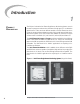
Introduction 1 PRODUCT DESCRIPTION The Eclipse Combustion Veri-Flame Single Burner Monitoring System controls the start-up sequence and monitors the flame of single gas, oil, or combination gas/oil burners. There are three different models to the Veri-Flame line: the no purge, the purge and the modulation models. Each model features field selectable trial for ignition (TFI). Each model is also available for use with four types of flame sensor: ultraviolet (UV), self-check UV, infrared (IR) and flame rod.
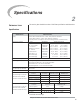
Specifications 2 INTRODUCTION This section gives a detailed overview of Veri-Flame specifications and dimensions. Specifications PARAMETER Supply Temperature Ranges DESCRIPTION • Series 5602 & 5605: 120 VAC (+10%, -15%), 50/60 Hz standard. Series 5603: 240 VAC (+10%, -15%), 50/60 Hz standard. Internal power consumption: 12 VA (excluding external connected loads). Unit Model Nos. Temperature Range Veri-Flame All Models -40˚ to +60˚C (-40˚ to +140˚F) 90˚ U.V.
Specifications (continued) PARAMETER Approvals (See chart below.) DESCRIPTION • No Purge & Purge Models: Series 5602: UL listed, CSA certified, FM approved and IRI acceptable. Series 5603: No approvals. Series 5605: UL listed, FM approved and IRI acceptable. • Modulating Models: Series 5602: UL recognized (must be mounted in panel), CSA certified, FM approved and IRI acceptable. Series 5603: No approvals. Shipping Weight • 1.4 kilograms (3 lbs.) for all Veri-Flame models. • 0.9 kilograms (2 lbs.
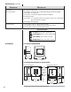
Dimensions (continued) Veri-Flame/Modulating Model with Base Model Number 5602-40 24mm (15/16") 171mm (6-3/4") 25mm (1") 1 2 3 4 5 6 7 8 A D S2 S1 10 11 12 13 40mm (1-9/16") 5mm (3/16") 10mm (3/8") 213mm (8-3/8") 116mm (4-9/16") Remote Display Model Number 5602-DB 102mm (4") Square * 54mm (2-1/8") 89mm (3-1/2") Square Ground Screw Mounting Bracket & Screw (2) Contrast Adjustment Screw * * = Alternate Mounting Locations Wiring Terminal 15-pin Port Terminal 24VDC Power Supply for Remote Display
DIP Switch Selection 3 INTRODUCTION This section details the location, selection and description of the Veri-Flame DIP switches, which allow for sequence and timing functions as well as system configuration. Caution To avoid electric shock, shut off the power supply when installing or removing any control device. Flame monitoring systems must be installed by a qualified, licensed technician. DIP Switch Location All of the DIP switches are located in the back of each Veri-Flame unit (see Figure 3.
Figure 3.1 DIP Switch Location Close-up of DIP switches on back side of all Veri-Flame models. Figure 3.
Function Summary 4 INTRODUCTION This section describes the features of theVeri-Flame. It is broken into three categories: Standard features, Optional features and the LED Indicator Lights on the front cover. Refer to Figure 5.5 for sequence diagrams. STANDARD FEATURES The following function features are standard on the Veri-Flame models as noted: Interlocks and Limit Switch Input (Terminal 7) This input is considered the normal operation control or run input to the VeriFlame system.
Main Fuel Valve Closed/ High Fire Purge Check (Terminal D) For modulation models: This feature is enabled when the jumper on the base is cut. The system checks that the high fire position switch and the main valve closed switch are both made at the end of the high fire purge. Recycle Mode For all models: when selected, the Veri-Flame will restart the sequence after flame or air failure.
System Errors & Lockout Conditions (Continued) 4) Low fire fail (for modulating model)–low fire switch open prior to trial for ignition. 5) High fire fail (for modulating model)–high fire switch is not closed at the end of high fire purge. The following situations will result in a lockout condition: 6) Air failure (for purge and modulation models) – loss of combustion air anytime during the operational cycle. The Air Failure LED will be on for this condition. (See “Recycle Mode”).
OPTIONAL FEATURES The following features are available on select models, or when optional equipment is purchased. Air Switch Input Hold For purge/modulation models: holds the sequence indefinitely until air switch input is confirmed without affecting the air failure function and causing a lockout. Remote Display & Power Supply Two models of remote display are available. The model 5602DB operates on 24VDC and has no keypad. The model 5602DBP operates on 120VAC and has a keypad for reset function.
System Installation 5 INTRODUCTION In this section, the necessary procedures are detailed to integrate a Veri-Flame into a burner system; Figures 5.1 and 5.2 illustrate the various terminal strips mentioned. Note: Shut off the power supply before the Veri-Flame is removed or replaced from the base. Caution: Installation and maintenance must conform with the National Electrical Code and all other national and local codes and authorities having jurisdiction.
Ignition Wiring Route ignition wiring a sufficient distance from all sensors and other low voltage wiring to avoid electrical interference, which may cause erratic operation of the Veri-Flame system. Keep the high voltage wire run from the ignition transformer as short as possible. The best condition is to mount the ignition transformer close to the burner and keep a low impedance path from the burner ground to the case of the transformer.
Figure 5.1 No Purge and Purge Wiring Diagrams Purge Models No Purge Models 5602/5605: 120 VAC 50/60 HZ 5603: 240 VAC 50/60 HZ 5602/5605: 120 VAC 50/60 HZ 15 A On/Off Fuse 15 A On/Off Fuse 1 1 Interlocks & Limits Piloted Burner 2 3 Pilot 3 Pilot 4 Ignition 4 Ignition 5 Main 5 Main Air Flow Switch 6 A Interlocks & Limits Alarm V 7 8 Alarm Proof of Closure V S1 G S2 G Figure 5.2 Modulation Wiring Diagram 5602/5605: 120 VAC 50/60 HZ 15 A.
Figure 5.3 Typical Connections For All Models Model 5602 DBP 120 VAC Remote Display Model 5602 DB 24 VDC Remote Display 12V 12V Tx + 24V G Tx Rx G Cable #20318 PLUG Flame Signal Test Jack To S2 120V 120V R1 L N Rx R2 G to 120 VAC Cable #20318 PLUG Veri-Flame To 1 Flame Signal Test Jack To S2 Veri-Flame Power Supply #20317 N G 120/240VAC U.V. / I.R. S1 Blue (Signal) S2 Yellow (Neutral) Solid State U.V. / I.R. U.V or I.R.
Figure 5.
Ignition 5 Main Valve 7 Interlocks V POVC Flame Check TFI Outputs Inputs Terminal Function 1 Control Power 3 Pilot Valve 4 Ignition 5 Main Valve 8 Fan 6 Air Switch 7 Interlocks V POVC Prov en 10 Sec TFI Outputs Inputs Function 1 Control Power 3 Pilot Valve 4 Ignition 5 Main Valve 8 Fan 6 Air Switch 7 Interlocks D High Fire & POVC 3 Low Fire Switch Continuity 10 to 12 Between Modulation 10 to 13 Terminals 10 to 11 35 Seconds Main Trial 10 Sec Recycle Perm
Sensor Installation 6 INTRODUCTION This section describes the proper wiring, installation and sighting considerations for all sensors that can be used with a Veri-Flame. Warning Incorrect sensor installation may cause the sensor to generate a false flame signal, possibly resulting in the collection of unburned fuel in the combustion chamber. This unburned fuel creates the potential for explosions which can result in injuries, death and property damage.
Figure 6.1 Flame Rod Position WRONG Rod Detects Weak Pilot CORRECT Rod Detects Only Strong Pilot Flame PILOT 1) Keep the flame rod as short as possible and at least 13 mm (1/2") away from any refractory. 2) Position the rod into the side of both the pilot and main flames, preferably at a descending angle to minimize drooping of the flame rod against burner parts, as shown in Figure 6.1. Flame rod position must adequately detect the pilot flame at all burner draft conditions.
Test Procedures 7 INTRODUCTION This section describes the test procedures that must be performed after installation to insure that the Veri-Flame is operating properly; these procedures are mandatory. Flame Signal Strength Insert the positive probe of a 0-15 VDC, digital volt meter into the test point on the front cover of the Veri-Flame; connect the negative probe to ground. A good flame signal strength will read between 6 and 11 VDC; anything below 4 VDC is inadequate.
Pilot Flame Failure Test 1) Manually shut off the fuel supply to the pilot and the main burner. 2) Place system in pilot test mode (please refer to page 15). 3) Start the system normally. The controller should lock out*; if it doesn’t, then the controller is detecting a false flame signal (see Section 6). Find the problem and correct it before resuming normal operation. Main Flame Failure Test 1) Manually shut off the fuel supply to the main burner but not to the pilot.
Maintenance &Troubleshooting 8 INTRODUCTION This section is divided into two parts: • The first part describes the maintenance procedures. • The second part describes troubleshooting procedures, from identifying problems to interpreting the operating conditions by the lit LEDs on the front cover. MAINTENANCE Preventative maintenance is the key to a reliable, safe and efficient system. The core of any preventive maintenance program is a list of periodic tasks.
TROUBLESHOOTING PROBLEM Cannot initiate start sequence POSSIBLE CAUSE Main valve is not closed. Air pressure switch has not made contact. SOLUTION Check main valve closed switch. No voltage on V (or D). Check air pressure switch adjustment. Check air filter. Check blower rotation. Check outlet pressure from blower. No voltage on 6 after 8 is on. High gas pressure switch has tripped. Check incomming gas pressure; adjust gas pressure if necessary. Check pressure switch setting and operation.
LED STATUS This section describes the status of operating conditions based on the LED or combination of LEDs which are lit on the front cover of each Veri-Flame model. Table 8.1 LED Status & Conditions for Veri-Flame No Purge Models LED(S) LIT POSSIBLE CAUSES INTERLOCKS CLOSED 1) The interlocks are closed (normal operation), power on terminal 7. SYSTEM ERROR 1) 2) 3) 4) 5) 6) The flame detected is out of sequence, flame signal light is on. The sensor is “runaway”, flame signal light is on.
Table 8.2 LED Status & Conditions for Veri-Flame Purge Models LED(S) LIT POSSIBLE CAUSES INTERLOCKS CLOSED 1) The interlocks are closed (normal operation), power on terminal 7. SYSTEM ERROR 1) 2) 3) 4) 5) 6) 7) 8) The flame detected is out of sequence, flame signal light is on. The sensor is “runaway”, flame signal light is on. Inductance is detected on sensor wires, flame signal light is on. Voltage wired into terminals 3, 4 or 5. Internal relay contacts welded. Internal controller failure.
Table 8.3 LED Status & Conditions for Veri-Flame Modulation Models LED(S) LIT POSSIBLE CAUSES INTERLOCKS CLOSED 1) The interlocks are closed (normal operation), power on terminal 7. SYSTEM ERROR 1) 2) 3) 4) 5) 6) 7) 8) 9) The flame detected is out of sequence, flame signal light is on. The sensor is “runaway”, flame signal light is on. Inductance is detected on sensor wires, flame signal light is on. Voltage wired into terminals 3, 4 or 5. Internal relay contacts welded. Internal controller failure.
Remote Display Messages 9 INTRODUCTION This section covers how the optional remote display is used with the Veri-Flame. The remote display provides LCD messages which monitor the status of the VeriFlame’s functions as well as any lockout conditions. This section is divided into two parts or tables: • The first table describes the start-up and shutdown monitoring sequences of the Veri-Flame and how the progress (or halt) of the sequence can be monitored by the messages on the remote display.
Table 9.1 Veri-Flame Operating Sequence POWER ON Was internal safe start check successful? NORMAL MESSAGE YES REMOTE DISPLAY REVISION X.X NO Various lockout messages EXTERNAL INTERLOCK CHECKS Is flame signal present? ERROR MESSAGE #1 YES UNSAFE FLAME ON Fan is energized. If signal is eliminated within 30 seconds, sequence continues. If not, then . .
Table 9.1 Veri-Flame Operating Sequence (continued) BURNER START-UP Is voltage present at air flow switch within ten seconds? NO PURGE MODELS MODULATION MODELS Is voltage present at air switch . . . PURGE MODELS NORMAL MESSAGE Is voltage present at air switch . . . AIR PROVEN YES NO ERROR MESSAGE NORMAL MESSAGE AIR PROVEN YES AIR NOT PROVEN XX:XX:XX LOCKOUT NO NORMAL MESSAGE Purge based on selected time.
Table 9.1 Veri-Flame Operating Sequence (continued) BURNER START-UP (continued) Is flame signal present? YES ERROR MESSAGE NO MAIN FLAME FAIL XX:XX:XX LOCKOUT NORMAL MESSAGE MAIN FLAME ON NORMAL MESSAGE MAIN FLAME ON PILOT OFF Pilot will shut off 10 seconds after main flame is energized.
Table 9.1 Veri-Flame Operating Sequence (continued) BURNER SHUTDOWN Shutdown is started by opening the operating interlock circuit. Is voltage present at interlocks? YES Continued operation. NO Is post purge selected? YES NO NORMAL MESSAGE POST PURGE XX Fuel valves de-energized; fan energized for 15 seconds. Is main valve closed switch made?* YES ERROR MESSAGE NO MAIN VALVE FAIL XX:XX:XX LOCKOUT Fan energized; alarm sounds.
Table 9.2 Remote Display Diagnostic Messages (Listed Alphabetically) MESSAGE 38 TYPE EXPLANATION AIR FAILURE XX:XX:XX LOCKOUT Lockout For purge & modulation models: Combustion air flow limit switch opened for more than two seconds once initially proven. AIR FAILURE RECYCLING Status For purge & modulation models: Combustion air flow limit switch opened; if “recycle” has been selected, the Veri-Flame will restart the sequence after air failure (see “Recycle Mode” on page 14).
Table 9.2 Remote Display Diagnostic Messages (continued) MESSAGE TYPE EXPLANATION MAIN FLAME ON Lockout Main valve has been energized and main flame proven during trial for ignition. MAIN FLAME ON PILOT OFF Status Pilot valve is de-energized and main flame is on. MAIN VALVE FAIL XX:XX:XX LOCKOUT Lockout For purge and no purge models: Main valve closed switch is open before start-up or after burner shutdown.
Table 9.2 Remote Display Diagnostic Messages (continued) MESSAGE 40 TYPE EXPLANATION UNSAFE FLAME ON Hold Flame signal—actual, induced, or runaway scanner—is detected before start-up or after shutdown. The fan is energized. If the cause is corrected within 30 seconds, as in afterburn, the control will turn off the fan and continue the sequence.
Appendix CONVERSION FACTORS Metric to English. FROM TO 3 MULTIPLY 3 cubic meter (m ) BY cubic foot (ft ) 35.31 cubic meter/hour (m /h) cubic foot/hour (cfh) 35.31 degrees Celsius (°C) degrees Fahrenheit (°F) kilogram (kg) pound (lb) (°C x 1.8) + 32 2.205 kilowatt (kW) Btu/hr 3414 meter (m) foot (ft) 3.28 millibar (mbar) inches water column ("wc) 0.401 millibar (mbar) pounds/sq in (psi) 14.5 x 10⁻³ millimeter (mm) inch (in) 3.
ILLUSTRATED PARTS LIST Category Pos. No. 1 2 3 4 5 1 Sensors 6 6 7 2 8 9 10 3 Bases 11 Test 12 4 Display Model Number Part Number Straight U.V. scanner NEMA 4 U.V. scanner 90˚ U.V. scanner I.R. scanner Self-check scanner Solid-state U.V./I.R. scanner 10-foot cable for self-check scanner Scanner support (max. temp. 220˚F) (1) Scanner support (max. temp.