SYSTEM INSTRUCTION MANUAL FOR AIRCRAFT GLIDERS - 7 CHANNELS - 7 MEMORIES - PROGRAMMABLE FM SHIFT www.hitecrcd.
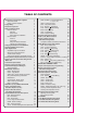
TABLE OF CONTENTS Introduction to the Eclipse 7 System About this manual Eclipse 7 System Options: Flying Safety Airplane Frequencies Radio Installation Notes Notes on Servos Mounting Servo Throw Switch Harness Installation Receiver Notes Antenna Connectors Using The Aileron Extension Vibration and Waterproofing Charging the Eclipse 7 Ni-Cd Batteries Operating With A Trainer Cord Other Adjustments Adjustable length control sticks Stick lever tension adjustment Throttle ratchet change Changing the Eclipse 7
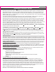
Model Setup Functions Introduction to the Eclipse 7 System Congratulations! You now own a Hitec Eclipse 7, an extremely versatile R/C system that may be effectively used by both beginning and master pilots. The transmitter may be programmed for airplanes, gliders, or helicopters, all with special mixing functions, so it can accommodate virtually any model configuration.
Model Setup Functions Flying Safety determine the cause of the problem. We recommend that you range-check your system before each flying To ensure your own safety and the safety of others, session. Have an observer verify that the system works please observe the following precautions: with the transmitter about 30 paces away with the Charge the Batteries! Be sure to recharge the batteries before each flying ses- transmitter antenna collapsed. Finally, before starting sion.
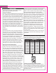
Model Setup Functions Radio Installation Notes running and the model should be securely restrained While you are installing the battery, receiver, and servos in case of loss of control. Connectors into your model's fuselage, please pay attention to the Be sure the alignment of a servo or battery connector is following guidelines: correct before inserting it into the receiver.
Model Setup Functions view shown. Using a small cross-point screwdriver, To use the trainer cord: 1 Set up both the student's and instructor's transmitters rotate the adjusting screw for each stick for the desired to have identical trim and control motions. If the instruc- spring tension.
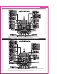
Model Setup Functions Eclipse 7 "Mode 2" Controls and Switch Assignments This figure shows the assignments for a Mode 2 system as supplied by the factory in North America. Note that some of the functions will not operate until activated in the mixing menus. Eclipse 7 "Mode 1" Controls and Switch Assignments This figure shows the assignments for a Mode 1 system as supplied by the factory (not in North American versions).
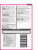
Model Setup Functions Transmitter Input Buttons The buttons are used for different things as follows: 1. The Edit/Display Up & Down buttons (1)allow you to move up and down within the model menus, and move within the regular display. 2. The Cursor Left/Right buttons (2)allow you to select options within a particular function, and control the timer function. 3. The Data +Increase & -Decrease buttons (3)allow you to increase or decrease the numerical settings for a function. 4.
Model Setup Functions Pressing the Up button again gives the Model Name display. If you've named your model, it will appear here so you can be sure you have recalled the correct memory. If you do not name the model, you'll have to remember which model memory it's stored within by the memory number. Pressing the start/stop button gives the Timer display, with a stopwatch display on the left, and operating time on the right. This also starts the timer, so hit the start/stop key again to stop it.
Model Setup Functions THE OLD SETTINGS IN THE SLAVE MODEL MEMORY, MODL - Model Select Your Eclipse 7 system can store up to seven independ- SO BE SURE YOU'RE IN THE CORRECT MODEL ent sets of model data in its memory. The Model Select BEFORE YOU COPY MODEL! 5. Switch power off. (MODL) function allows you to choose from any of the 6. Switch power back on. If you wish to go to the newlyseven sets of model data. saved memory, repeat step 1.
Model Setup Functions provide these functions (120', 180'). Note that these menus will not be available unless you have selected the GLID or HELI model types. Selecting the Wing or Swashplate Type 1. Select the GLID or HELI model type in the Model Type Select menus (see above). 2. With the transmitter switched off, turn on your transmitter while pressing both of the two Edit keys (the two keys on the far left). The model select (M.SEL) menu will be displayed. 3.
Model Setup Functions the servos will move erratically and will not respond to the transmitter, even if it is on the correct frequency. Turn off your receiver at once to preclude damage to your servos, and change the shift direction. If you use a mixture of receiver brands, make sure that the transmitter is properly set for the brand of receiver you are using in the current memory. Changing the Frequency Shift 1.
This section describes the menu functions for fixed-wing aircraft, provides a detailed setup example, and then describes the functions individually. Functions relating specifically to gliders and helicopters may be found in the following sections. ACRO Functions Map (see right) Simple Aerobatic Airplane Transmitter Setup 13 EPA D/R EXP FLT.C S.TRM REV T.
Aircraft(ACRO) Section 9. Repeat two more times to fill out the remaining two letters. If you like, you can hit the right cursor button one more time and select a number between 0 and 199 for further identification. It can be handy to use this to store the plane's channel number. 1O. Press the Up arrow once. This gets you into the Timer menu (TIME). If you want, you can use the Data +Increase or -Decrease keys to select the amount of time you want the stopwatch to count down. 11.
Servo Pushrod 90 Adjust the clevises on each servo pushrod to get the position of each control to be as close as you can to neutral (lined up with the adjacent portion of wing or tail). Setting Subtrims. Now we'll adjust all the subtrims to electronically set the desired neutral locations. To do so, go back to the programming menu by pressing both Edit keys, then press the Up or Down arrow key repeatedly until STRM appears. 26. Set the right aileron subtrim first.
Aircraft(ACRO) Section control motions specified on the plans or instructions by the model's designer. 35. To set travels, get to the EPA menu by pressing one of the Up Down Edit buttons repeatedly until EPA Changes from L/U to R/D with AIL stick motion Flashing appears. In sequence,we'll set right aileron right travel,right aileron left travel, up and down elevator travels, right and left rudder travels, open and closed throttle positions, and left aileron travels. 36.
Aircraft(ACRO) Section proportional. 58. With landing mode on, it is possible to lose some aileron effectiveness. Be sure to test the landing settings at altitude before trying it on a landing approach. You should spend some time fine-adjusting the elevator travel so that there is minimal trim change when the landing (Flt. Mode) switch is operated. 59. Press one of the Up Down Edit buttons until the LAND window appears, as shown. The landing mode is OFF unless the ON or OFF depends on Flt.
Aircraft(ACRO) Section numeral 4, indicating CH4 (rudder) is the master channel. Press the Cursor Right key once (SLV flashes on and off), then press the Data +Increase key until the little arrow is under the numeral 2, indicating CH2 (elevator) is the slave channel. 68. Now, you'll define the mixing percentage. Notice that the mixer starts with 100% on both sides, which is WAY too much. Move the rudder stick to one side and press the Clear button, zeroing the percentage.
This figure shows the assignments for a Mode 2 system as supplied by the factory for the North American version. Note that some of the functions will not operate until activated in the mixing menus.
Aircraft(ACRO) Section position with zero exponential, and an exponential value with 100% dual rate at the other. Then you can switch between them in flight and decide which you like better. Later, you can combine both dual rate settings and exponential on a single switch setting. There are really two kinds of exponential, "positive" and "negative.
Aircraft(ACRO) Section 6. Now that you have activated one or more flight conditions, you can have new sets of dual rates, exponential values, and trims. Trims are defined by the trim levers on the transmitter, but you can define the values of D/R and Expo using the programming menu. Use the Edit Up Down key to move to the D/R menu. 7. With D/R indicated in the display, be sure the flight condition switches are in the desired position by checking to see which is flashing.
Aircraft(ACRO) Section REV - Servo Reversing The servo reverse function may be used when you need to change the direction that a servo responds to a control stick motion. When you use this function, BE SURE THAT YOUR CONTROL IS MOVING THE CORRECT DIRECTION. If you are using any preprogrammed mixers such as flaperon, be sure to set correct travels in the REV menu setting up the preprogrammed function. Reversing Servos 1. Get to the REV screen with the Edit Up Down keys. 2.
the recommended starting value. Be careful as this has a very powerful effect on the model's trim. Press the Active/Inhibit (Clear) key if you wish to reset to 0%. 3. To get to the flap travel setting, press the Cursor Right key. The small triangle is now displayed above the numeral 6, indicating the flap channel. You may input any desired flap travel with the Data +Increase and -Decrease keys.
Aircraft(ACRO) Section Setting Up E F Mixing 1. Press one of the Up Down Edit buttons until the E->F window appears. The default is for the function to be inhibited. To activate, press the Active/ ON or OFF depends on Flt. Mode switch setting Inhibit (Clear) key. This will cause the INH display to change to a number display, and either ON or OFF will be flashing depending on the position of the Flt. Mode switch (fully aft turns it ON). 2.
motion has occurred. Therefore, you should keep the travel settings at 50% or below and adjust the control linkages to get the travel you desire. Note that you can not have both V-tail and elevon mixing active at the same time. CH2 CH4 Up Elevator CH2 CH4 Left Rudder (view from rear) Setting up V-Tail mixing 1. The right ruddervator should be plugged into CH2, and the left ruddervator should be plugged into CH4. 2. Press one of the Up Down Edit buttons repeatedly to select the VTAL window.
Aircraft(ACRO) Section -Decrease keys. 50% is a good starting point. Press Active/Inhibit (Clear) key if you wish to reset to 0%. 8. Remember to be sure not to have so much travel as to cause binding when both elevator and rudder are commanded simultaneously. FLPN - Flaperon Mixing The Flaperon mixing function uses two servos to individually control two ailerons, combining the aileron function with the flap function. Both ailerons can be raised and lowered simultaneously for a flap effect.
The following chart may be used to systematically set up and trim a model for straight flight and aerobatic maneuvers. Please note that for best results, trimming should be done in near-calm conditions. Before you decide to make a change, be sure to try the test several times before making adjustments. If any changes are made, go back through the previous steps and verify that they are not also affected. If they are, make further adjustments as necessary. To test for ...
Test Procedure Observations Adjustments 10. Dihedral Method 1: Fly the model on normal pass and roll into knife-edge flight; maintain flight with top rudder (do this test in both left & right knifeedge flight) Method 2: Apply rudder in level flight A. Model has no tendency to roll B. Model rolls in direction of applied rudder C. Model rolls in opposite direction in both tests 11.
Glider(GLID) Section Eclipse 7 Glider Controls and Switch Assignments This figure shows the assignments for a Mode 2 system as supplied by the factory for the North American version. Note that some of the functions will not operate until activated in the mixing menus.
Glider(GLID) Section Competition Glider Quick Setup Instructions The following example shows how the Eclipse 7 may be programmed for the "typical" high-performance six-servo sailplane, shown below. Six servos are used for right and left ailerons, right and left flaps, elevator, and rudder. If the model happens to have a V-tail, all the functions are the same, except for the response of the two tail controls.
the Camber knob (VR1 knob) goes into both positive and negative camber from the neutral point, unless you set the F A offset (see previous step). 22. Center the camber knob, also known as the VR1 knob, on the top left of the transmitter. Be sure to center all of the trims, and get all of the servo arms to be near neutral. Use the clevises to get as close as you can. This way you won't run out of subtrim authority.
Glider(GLID) Section needed to trim. Press the Cursor Right key once to get to the elevator setting menu (a small triangle appears over the number 2). Set the desired number with the Data +Increase or -Decrease keys. For starters, use zero or very little elevator compensation until you fly and determine what is needed: if the model pitches up with crow, add down elevator compensation and if it pitches downwards,add some up compensation.
differential Coordinated turn fuse lines up with turn direction (don't change anything!) Nose Points inside circle Too much coupling or differential. Reduce one or both. Setting Up Differential 1. Press one of the Up Down Edit buttons repeatedly to select the ADIF window. To begin with, the function is already activated, but it's set to 100% on both sides so there is no differential. 2. A small arrow is displayed under the numeral 1, showing that CH1 is the affected channel.
Glider(GLID) Section 3. Make sure CROW is ON by moving the Gear switch forward. Verify by looking at the flashing indicator. 4. Next, set up the throws for the ailerons. Press the Right key two times to get to the aileron setting menu (a small arrow will appear over the number 1 in the display). Press the Data +Increase or -Decrease keys to adjust the amount of UP aileron motion. Move the throttle stick all the way down and be sure the ailerons go UP.
Caution: when setting up crow, do not call for too much aileron "up" travel, or you'll lose roll authority, and this occurs at a crucial time, when your model is flying relatively slowly on a landing approach. Always make changes in small increments, don't try to do it "all at once." S.TM1, 2 - Speed Flap Trim offsets (Camber mix) 1, 2 (4WNG only) Speed Flap Trim Offsets, together with flight conditions, are a way to set up gliders with four wing servos(4WNG).
Glider(GLID) Section Using Aileron->Flap Mixing 1. Turn on Aileron->Flap mixing by locating the A->F menu with the Up Down Edit keys. The default is for it to be inhibited (Inh). Press the Active/Inhibit (Clear) key so that the 'On' display is shown. 2. First, you'll set the aileron (CH1)->CH6 function mixing amount. Make sure A->F is On by moving the Flt. condition switch fully back. Verify it's on by looking at the flashing On indicator.
Test Procedure Observations 1. Model Control Neutrals To test for ... Fly the model straight and level 2. Control Throws Note: be sure all aileron & flap horn pairs have matching angles Fly the model and apply full deflection of each control in turn. Camber control in neutral (setup 6 & 9). Trim for level glide. Enter 45 dive (across wind if any) and release controls. CAUTION: beware of airspeed & flutter. Adjust the transmitter trims for hands-off straight & level flight, no camber control.
Helicopter(HELI) Section Eclipse 7 Helicopter Controls and Switch Assignments This figure shows the assignments for a Mode 2 system as supplied by the factory for North America. Note that some of the functions will not operate until activated in the mixing menus.
Eclipse 7 Helicopter (HELI) Programming Helicopter Functions Map Helicopter Setup Example R->T GYRO HOLD THCV PTCV RVMX SWAH Hovering Hovering see right 39 Rudder->Throttle mixing Gyro Settings Throttle Hold Throttle Curve Pitch Curve Revolution mixing Swashplate settings (120', 180') Pitch Adjusting knob Throttle Adjusting knob 42 42 42 43 43 44 44 45 45 Voltage/Timer Display Normal Display Mode Press both Edit/Display keys End Point Adjust [EPA] Dual Rate Set [D/R] Exponential [EXP] Sub-Trims [STM]
Helicopter(HELI) Section both Data keys to "Save" the setting. This is how you select the type of model you wish to use, either ACRO, HELI, or GLID. 180' swash types, please use the swashplate (SWAH) menu, page 44, to adjust these responses. DOWN Right Aileron: swashplate tilted Flashing LEFT WARNING: selecting a different model type will erase the settings in the model memory.
Point % 1 (low) 0 2 26 3 45 4 72 5 (high) 100 Point % 19. Pitch Curve. You can use the Pitch Curve(PTCV) menu's five-point setting curves to make finer adjustments to the endpoints and the middle of travel of the pitch servo. Your model's instructions may provide suggested values for the blade pitch angles. If not, you may want to start with the following: Pitch Curve NOR Point Pitch 1 (low) 0 deg. 2 +5 3 +6.5 4 +8.
Helicopter(HELI) Section These conditions are activated whenever the model memory is chosen to be HELI type. These flight conditions are switched on as follows: NOR: ON when Flt. Mode Switch is back. ST1: ON, when Flt. Mode Switch centered ST2: ON when Flt. Mode Switch is forward. ST3: ON when Flt. Cond Switch is forward. As these functions are switched on or off, ST3 = HOLD has highest priority, followed by ST2 and ST1. Regular settings (NOR) occur when all of the others are off.
appear over the number 1 in the display, and a value of 0% should be shown. Press the Data +Increaseor -Decrease key to change the setting to your desired value. 4. When you're finished with Point 1, move to the next point with the Cursor Right key. A small arrow over the number 2 indicates you are setting the value for Point 2. Note that the function is inhibited (Inh) to start with. If you leave it, you get a straight line from points 1 to 3.
Helicopter(HELI) Section If you leave it, you get a straight line from points 1 to 3. Otherwise, you can change this setting with the Data +Increase or -Decrease keys. You can inhibit THCV point 2 and 4 by pressing the clear key. 5. Repeat this procedure for Points 3, 4, and 5 by pressing the Cursor Right key, then adjusting as desired with the Data +Increase or -Decrease keys. 6. When you've completed the settings for the first flight condition (NOR), test fly your model.
Changing the HV-T value moves the throttle response above or below the straight line Hover High Throttle Stick Motion Collective Pitch Servo Response Hovering Pitch Adjustment Knob Max The Hovering Pitch Pitch knob may be used to trim the collective pitch near hover without affecting throttle.
GLOSSARY The abbreviations used with the Eclipse 7 are defined below alphabetically. Related pages are given in parenthesis following the definition. A ACRO ADIF AIL.T ATL A->F A->R C camber F FLPN Acrobatic aircraft menu (13) Aileron differential. Makes aileron move more to one side than the other (32) Dual aileron trim (35) Adjustable Travel Limit. Limits throttle trims to only the throttle idle position. (built in to your system) Aileron Flap mixing (35) Aileron Rudder mixing (24) FLT.
GLID Model Data Recording Sheet Make copies before using Model Name ___ ___ ___ ___ -__ __ __ MENU FUNCTION REV Servo Rev (circle) EPA End Point Adj.
Austria, Belgium, Denmark, Finland, France, Germany, Greece, Iceland, Ireland, The Netherland, Italy, Spain, Norway, Portugal, United Kingdom, Luxembourg, Sweden, Switzerland www.hitecrcd.