
Instruction manual


Flap Ail Mix [F -A]
28
*Trim tab is 3/16" x 3/4" x 4" trailing edge stock, placed just in front of aileron on bottom, pointed end forward.
Glider (GLID) Menu Functions
Gear Switch controls receiver CH3
VR1 controls camber (flap motions)
VR2 controls receiver CH7 and sets DFL.T
CH7 switch Forward = F->A On, F->E On
Useful Control & Switch Information
GEAR switch Back = CROW Off,
Flt. Condition switch Back= A->F Off
Flt. Mode switch Back ("speed")= E->F On, S.TM1
Flt. Mode switch Forward ("launch") = S.TM2 On
28
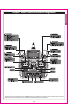
Glider Functions Map (see right)
Glider Setup Example 30
EPA End point adjust 18
D/R Dual Rates 18
EXP Exponential 20
FLT.C Flight Condition 20
S.TRM Subtrim 21
REV Servo Reverse 22
PMX1-5 Programmable Mixer #1- #5 22
ADIF Aileron Differential 25
VTAL V-Tail 25
E->F Elevator Flap mixing 23
A->R Aileron Rudder Coupling 24
F->A Flap Aileron mixing 33
F->E Flap Elevator mixing 33
CROW Crow mixing (airbrakes) 34
AIL.T Aileron Dual Trim 35
S.TM1, 2 Speed Flap trim offsets 1, 2 (GLID4) 35
A->F Aileron Flap mixing (GLID4) 35
DFL.T Dual Flap Trim knob (GLID4) 36
Glider Trimming Chart 37
Voltage/Timer Display
Normal Display Mode
Press both
Edit/Display keys
4
4
4
4
4 = 4WNG only
The following section describes how to use the glider-specific menu functions
(model type GLID). Descriptions of the other functions are contained in the
aircraft (ACRO) section. There are two different glider modes in the Eclipse 7
system. You set them up in the Model Setup menus (see page 10). 4WNG
refers to a glider with four wing servos. 2WNG refers to a model with two
wing servos for flaperons, but this setup also applies to models with an
additional flap or spoiler servo in CH6.
To test for ...
10. Dihedral
11. Elevator alignment
(for models with
independent
elevator halves)
12. Pitching in
knife-edge flight
Test Procedure
Method 1: Fly the model on normal
pass and roll into knife-edge flight;
maintain flight with top rudder (do
this test in both left & right knife-
edge flight)
Method 2: Apply rudder in level flight
Fly the model as in Test 6 and pull
up into an inside loop. Roll it
inverted and repeat the above by
pushing it up into an outside loop.
Fly the model as in Test 10
Observations
A. Model has no tendency to roll
B. Model rolls in direction of applied rudder
C. Model rolls in opposite direction in both tests
A. No rolling tendency when elevator applied
B. Model rolls in same direction in both tests
- halves misaligned.
C. Model rolls opposite directions in both tests.
One elevator half has more throw than the
other (model rolls to side with most throw).
A. There is no pitch up or down
B. The nose pitches up (the model climbs
to its top side)
C. Nose pitches down (model dives to its
bottom side)
Adjustments
A. Dihedral OK
B1. Reduce dihedral
B2. Use mixer to produce aileron
opposing rudder travel (start
with 10%)
C1. Increase dihedral
C2. Mix ailerons with rudder
direction 10%
A. Elevators in correct alignment
B. Either raise one half, or lower
the other
C. Reduce throw on one side, or
increase throw
on the other.
A. No adjustment needed
B. Alternate cures:
1) move CG back;
2) increase incidence;
3) droop ailerons;
4) mix down elevator with rudder
C. Reverse 'B' above
Glider(GLID) Section
Flap Ele Mix [F-E]
Ail Rud Mix [A-R]
Elev Flap Mix [E-F]
End Point Adjust [EPA]
Dual Rate Set [D/R]
Exponential [EXP]
Filght Cond. [FLT.C]
Sub-Trims [S.TRM]
Servo Reversing [REV]
Prog. Mix 1 [PMX1]
through
Prog. Mix 5 [PMX5]
Ail Differential [ADIF]
V-Tail [VTAL]
Crow Mix [CROW]
Subtrim Set 1 [STM1]
Subtrim Set 2 [STM2]
Aileron Trim [AIL.T]
Ail Flap Mix [A-F]
Dual Flap Trim [DFLT]