ECLIPSE® EA2000/EA4000 Ownerls Manual 2 / 4 Channel Integrated Series Power Amplifier 0 0 EA2000 L'ECLIPSE ~. ,,,.~. u _ LOW'OSI """'" 0 "'ASI ~~, !OO -0 100> 6 ", 00 - 00~ I'tZSlO:IO 0. 01' SPEAKER 001 lIIl '" UTIO IIIQf1 0 PIIU'" ~ 0 0 19°0-01 •. 'USE IllID6ED _ UU o LJ- TT.AEIlOIE GICI 10001 0 o EA4000 L'ECLIPSE o uuu Thank you for purchasing the EA2000(2 channel) I EA4000(4 Channel) Intergrated Series Power Amplifier. Please read this Owner's Manual before use.
Table of contents For your safety in using the EA Series Amplifiers 3 About Your Amplifier 4 Installation Requirements 5 Power Amplifier Adjustments and Tuning 6 Names and Functions of Terminals 9 Basic System Connection 10 AVN Connection Examples 11 Head Unit Connection Examples 12 Troubleshooting 13 Specifications 16 -2-
For your safety in using the EA Series Amplifier Warnings and caution signs, illustrated below, are posted throughout this manual as well as on the EA2000/EA4000. They show safe and correct ways to handle the product to prevent personal injury to you and others and to avoid damage to property. Before reading through the manual, take time to read through and learn the important information listed in this section.
About Your Amplifier Your Eclipse Power Amplifier was Designed and Engineered in the USA for the best in performance with the best components possible. In order to optimize the best performance of your system, we recommend a professional installation by an authorized Eclipse Dealer. Power Supply: All Eclipse Amplifiers incorporate Powerful MOSFET Switching Power Supplies for added reliability and powerful Music Reproduction.
Installation Requirements Before You Start: Congratulations on your purchase of this Eclipse Power Amplifier. The proper installation and system integration of this Power Amplifier will bring the optimum conditions for high performance and a long trouble free life for your Mobile Audio System. Please pay attention to the Installation hints listed in this section for the best results. 1.
Power Amplifier Adjustments and Tuning High Pass Filter: Stops the Low frequencies, allows all frequencies above the adjusted crossover point to be amplified. ~'" FILTER LJ Low Pass Filter: Stops the High frequencies, allows all frequencies below the adjusted crossover point to be amplified. LOW PASS 100 ....
4. System Power Up: Initial Tuning: Once the system is turned on and it is verified that all channels are functional, you may load your choice of Media to set the system levels with. Media with a good level, or lots of energy including drums, bass, voice etc is advisable. The gain controls should be adjusted with the tone controls set to flat position and the balance and fader in the center positions on the source unit.
Quick Set Up Process 1. Set Crossover Points before installing the Amplifier based on Speaker Size and System Configuration. 2. Turn the Gain Controls down before installing the Amplifier. 3. Turn the Bass Boost Control down, before installing the Amplifier. 4. Test the speaker wires to guarantee there are no shorts to the Car Body before connecting to the Amplifier. 5. Connect the B+ Power, Power Ground and Remote wires to the Amplifier. 6. Connect the Speaker Wires to the Amplifier. 7.
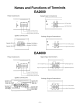
Names and Functions of Terminals EA2000 Power Connections Signal Input Connections 3" +BATT. REMOTE LINE IN @ FUSE GND.
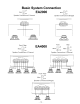
Basic System Connection EA2000 ~o l JON Mono LJ Mono lOFF Speaker Connections 2 Channel ~ JON R LJ 1 OFF Speaker Connections Bridged SPEAKER OUT +LEFT_ + , r==="J , +"IGHT_ BRIDGED , r==="J + + Front / Rear Mono l JON ~o EA4000 LJ Front Mono lOFF Speaker Connections 4 Channel .
AVN Connection Examples AVN Connections Internal Power + Subwoofers . EA2000 II. _.III E8. : Non-Fader Out ': Left Channel ~ ~ 1::::::=======I==F======:l Right Channel , , Front Left Speaker Front Right Speaker Front Rear Left Speaker Rear Rear Right Speaker AVN Connections EA4000 example of 3 channel install EA4000 .. •• Sub Front Out Non-Fader Out Front AVN connection using the EA2000 and EA4000 EA2000 Bridged Non Fader Out .. Front EA4000 • • Front Out Rear Out l...
Head Unit Connection Examples Head Unit Connections Internal Power + Subwoofers Left Channel Non-Fader Out ~~~ .
Troubleshooting If a problem occurs after your system is installed, please refer to this troubleshooting section for solutions. If after carefully following these instructions you still have a problem, please contact Eclipse Technical Supporl at 1-800-233-2216 Problem Possible Cause 1. Amp won't power on No fuse installed in the amplifier or fuse is blown Install fuse. Battery B+ not Powered on Check for 12V at Amp B+ Terminal: Make sure B+ Cable is connected to the Battery.
Problem Possible Cause 5. Amp has engine noise Speaker ground is shorted to car body 6. Distorted Output Test for negative speaker speaker short: Make sure negative speaker lead is not shorted to vehicle chassis or body. Outer barrel of RCA connector is shorting to the Amplifier chassis With amp off. disconnect RCA Cables And test for the impedance between the Barrel of the RCA and the amp power ground. If no negative speaker lead short, the impedance is nearly shorted (low resistance).
Problem Possible Cause 9. Speaker pops when Source unit may be sending pop noise to unit is turned on or off amplifier Possible Solution Disconnect RCA inputs then turn source unit on and off: If pop noise is gone try a different Source Unit. Possible ground loop noise Check to make sure grounds are correct so No ground loops can exist: If a poor ground exists correct the grounding.
Specifications Power Output: RMS Power at 14.4 Volt Power Supplv@ < .1% THO -------------EA2000------------60WX2 4 n @ 20 Hz to 20 KHz Stereo 175W X 1 4 n @ 20 Hz to 20 KHz Bridged @ 20 Hz to 20 KHz Stereo ( CEA 2006 ) <1 % THO 4n -------------EA4000------------75WX4 4 n @ 20 Hz to 20 KHz Stereo 150W X2 4 n @ 20 Hz to 20 KHz Bridged 4 n @ 20 Hz to 20 KHz Stereo ( CEA 2006 ) <1 % THO Max Power Output: Peak Music Power at 14.
- 17 -
- 18 -
- 19 -
CUSTOMER NOTICE Please retain this booklet and write in the serial number of your new Amplifier for identification. The serial number is labeled or stamped on the chassis. Serial No. FUJITSU TEN LIMITED Contact: FUJITSU TEN CORP.OF AMERICA 19600 So. Vermont Avenue, Torrance, CA 90502 800·233·2216 www.eclipse-web.com "ECLIPSE" is a registered trademark of FUJITSU TEN LIMITED in 48 countries including the U.S. and Japan.
LECLIPSE IMPORTANT SHOULD YOU HAVE ANY QUESTIONS, call: 1-800-233-2216 OJ FUJITSU TEN FUJITSU TEN CORP. OF AMERICA 19600 S. Vermont Avenue, Torrance, CA 90502 PLACE FIRST-CLASS STAMP HERE FUJITSU TEN CORP. OF AMERICA Warranty Registration 19600 S.
ECLIPSE LIMITED WARRANTY Eclipse (a division of Fujitsu Ten Corp. of America) hereby warrants your Eclipse product to be free from defects in material and workmanship for a period of one year from the original date of purchase. This warranty applies only to the original consumerpurchaser (this warranty is not transferable), and only when this product is originally purchased from an authorized Eclipse retailer in the United States or Canada.