
User manual


7
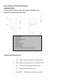
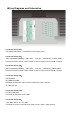
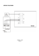
Wiring Diagrams and Schematics
Connection block CN1:
18V (RED), GND (BLK):Terminals for Power Supply Input
Connection block CN3:
,KEY1+(SDOOR1) (BRWN)、 VD1 (YEL)、 AU1 (W)、 GND (BLK) 、PWR1 (RED)
T
erminals
for
P
ower Unlock
/ Video /
A
udio /
Ground / supply
for
the
Doorbell / camer
a1.
Connection block CN4:
,KEY1+(SDOOR1) (BRWN)、 VD1 (YEL)、 AU1 (W)、 GND (BLK)、PWR1 (RED)
T
erminals
for
P
ower Unlock
/ Video /
A
udio /
Ground / supply
for
the
Doorbell / camer
a1.
Connection block CN5:
Standby Block
VD3,GND,AD3,GND:
Terminals for Extension Audio / Ground / Extension Video / Ground
J1: 75R jump line
Connection block CN6:
VD4,VD5,VD6,GND:
Terminals for Extension Video / GND
Connection block CN7:
+18V, GND, DATA, AU, VD, GND:
Terminals for Power+/ Power Ground / Data / Audio / Video / Video Ground