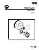
Design Guide No.110 12/01 RatioMatic Burners RM Series Version 3.
COPYRIGHT Copyright I998 by Eclipse Combustion, Inc. All rights reserved worldwide. This publication is protected by federal regulation and shall not be copied, distributed, transmitted, transcribed or translated into any human or computer language, in any form or by any means, to any third parties, without the express written consent of Eclipse Combustion, Inc., Rockford, Illinois, U.S.A.
About this manual AUDIENCE This manual has been written for people who are already familiar with all aspects of a nozzle-mix burner and its add-on components, also referred to as “the burner system.” These aspects are: • design/selection • use • maintenance. The audience is expected to have had experience with this kind of equipment. RATIOMATIC DOCUMENTS Design Guide No.
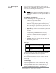
DOCUMENT CONVENTIONS There are several special symbols in this document. You must know their meaning and importance. The explanation of these symbols follows below. Please read it thoroughly. Danger: Indicates hazards or unsafe practices which WILL result in severe personal injury or even death. Only qualified and well trained personnel are allowed to carry out these instructions or procedures. Act with great care and follow the instructions.
Table of Contents About this manual . . . . . . . . . . . . . . . . . . . . . . . . . . . . . . 3 Audience . . . . . . . . . . . . . . . . . . . . . . . . . . . . . . . . . . . . . . . . 3 RatioMatic Documents . . . . . . . . . . . . . . . . . . . . . . . . . . . . 3 Related Documents . . . . . . . . . . . . . . . . . . . . . . . . . . . . . . . 3 Document Conventions . . . . . . . . . . . . . . . . . . . . . . . . . . . . 4 How to Get Help . . . . . . . . . . . . . . . . . . . . . . . . . . . . . . . . .
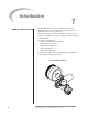
Introduction PRODUCT DESCRIPTION 1 The RatioMatic Version 3.10 is a nozzle-mix type burner designed for direct air heating, indirect air heating, and oven applications up to 1800° F. (1000° C.) The burner package includes a combustion air blower and an air:gas ratio regulator to fire over a wide gas turndown range at a controlled ratio.
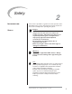
Safety INTRODUCTION SAFETY 2 This section is provided as a guide for the safe operation of the RatioMatic burner system. All involved personnel should read this section carefully before operating this system. Danger: The RatioMatic burners, described herein, are designed to mix fuel with air and burn the resulting mixture. All fuel burning devices are capable of producing fires and explosions if improperly applied, installed, adjusted, controlled, or maintained.
CAPABILITIES OPERATOR TRAINING REPLACEMENT PARTS 8 Only qualified personnel, with good mechanical aptitude and experience on combustion equipment, should adjust, maintain, or troubleshoot any mechanical or electrical part of this system. The best safety precaution is an alert and trained operator. Train new operators thoroughly and have them demonstrate an adequate understanding of the equipment and its operation.
System Design DESIGN 3 Design structure The design process is divided into the following steps: 1. Burner Option Selection including: • Burner Model / Size Selection • Fuel Type • Air Supply • Combustor Type • Combustor Length • Control Motor • Burner Configuration • Gas Pipe Connection • Flame Supervision • Air Flow Switch 2. Blower Option Selection including: • Power Supply Frequency • Pressure & Flow • Blower Motor Type • Blower Inlet • Motor Orientation 3.
Step 1: Burner Option Selection Step 1 describes how to select burner options to suit an application. Use the RatioMatic Price List 110 and Data Sheets, Series 110 when following this selection process. Caution: Consult EFE-825, Eclipse Combustion Engineering Guide, or contact Eclipse Combustion if you have special conditions or questions. Burner Model / Size Selection Consider the following when selecting the burner size: • Heat Input.
Nozzle position Nozzle Combustor Combustor length Configuration selections: Combustor Length Select a combustor length. Optional lengths are available on some models. Nozzle position will vary with combustor length. The nozzle position determines the location of heat release. Control Motor Select a control motor. Standard control motor options include various models which Eclipse will mount to the burner. RatioMatics can be ordered with control motor bracket and mounting hardware only.
Step 1: Burner Option Selection (continued) cause a fire or an explosion. Air Flow Switch The air flow switch provides a signal to the monitoring system when there is not enough air pressure from the blower. If a switch is selected, it will be factory mounted. Warning: Eclipse Combustion supports the NFPA regulation requiring, as a minimum standard for main gas shut-off systems, the use of an air pressure switch in conjunction with other system components.
Step 3: Control Methodology io ric on Excess air Gas Air/Gas Flow at He Air Butterfly Valve (BV) Control Motor Ga s F lo Loading Line • Ratio Regulator w A control signal is sent from a process temperature controller (sold separately) to the control motor. (Refer to Bulletin 818C or contact Eclipse Combustion for further information on temperature controllers.
Step 4: Ignition System Combustion. Ignition Transformer For the ignition system, use a transformer with: • secondary voltage 6,000 to 8,000 VAC. • minimum secondary current 0.02 amps continuous. • full wave output. DO NOT USE the following: • twin outlet transformer • distributor type transformer. Trial For Ignition It is recommended that low fire start be used. However, under certain circumstances RatioMatics are capable of direct spark ignition at higher gas inputs.
Step 4: Ignition System (continued) Ignition Gas Piping RatioMatics are capable of ignition with either low fire or bypass start gas. Low Fire Start: Main gas shut-off valve train Bypass Start Gas (optional): Main gas shut-off valve train NC Optional fuel orifice meter recommended An optional fuel orifice meter connected in the start gas piping can simplify start-up and adjustment. To start the burner at the lowest possible gas input, select a fuel orifice meter for 5” to 10” w.c.
Step 5: Flame Monitoring Control System Flame Rod The flame monitoring control system consists of two main components: • Flame Sensor • Flame Monitoring Control Flame Sensor Two types can be used on a RatioMatic Burner: • flame rod • U.V. scanner Flame rods are available for all RatioMatic Burner sizes. Further information can be found in: • Info Guide 832 U.V. Scanner A U.V. scanner can be used on all RatioMatic Burner sizes. Further information can be found in: • Info Guide 852; 90° U.V.
Step 6: Main Gas Shut-Off Valve Train Component Selection Eclipse Combustion can help in the design of a main gas shutoff valve train that satisfies the customer and complies with all local safety standards and codes set by the authorities within that jurisdiction. Contact Eclipse Combustion for further information. Note: Eclipse Combustion supports NFPA regulations (two gas shutoff valves as a minimum standard for main gas shut-off systems).
Appendix CONVERSION FACTORS Metric to English. From To Multiply By cubic meter (m3) cubic foot (ft3) 35.31 cubic meter/hour (m3/h) cubic foot/hour (cfh) 35.31 degrees Celsuis (ºC) degrees Fahrenheit (ºF) (ºC x 1.8) + 32 kilogram (kg) pound (lb) 2.205 kilowatt (kW) BTU/hr 3414 meter (m) foot (ft) 3.28 millibar (mbar) inches water column (“w.c.) 0.401 millibar (mbar) pounds/sq in (psi) 14.5 x 10⁻³ millimeter (mm) inch (in) 3.94 x 10⁻² MJ/m3 (normal) BTU/ft3 (standard) 2.
KEY TO SYSTEM SCHEMATICS Symbol Appearance These are the symbols used in the schematics. Name Remarks Bulletin/ Info Guide RatioMatic NC Main Gas Shutoff Valve Train Eclipse Combustion, Inc. strongly endorses NFPA as a minimum Gas Cock Gas cocks are used to manually shut off the gas supply on both sides of the main gas shut-off valve train. 710 Solenoid Valve (normally closed) Solenoid valves are used to automatically shut off the gas supply on a bypass gas system or on small capacity burners.
KEY TO SYSTEM SCHEMATICS (CONTINUED) Symbol Appearance Name Remarks Pressure Taps Impulse Line 20 Eclipse RatioMatic v3.10 - Design Guide No.
Offered By: Power Equipment Company 2011 Williamsburg Road Richmond, Virginia 23231 Phone (804) 236-3800 Fax (804) 236-3882 www.peconet.