
Service manual

Hydronic Heating Boilers and
Domestic Water Heaters
30
INSTALLATION
Continued
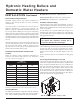
Water heater models do not have downstream test valves,
but the rest of the gas train is represented by Figure 29.
Combination Gas Valves
These units fire in multiple stages of burner input. Each
stage of burner operation has a combination gas valve(s)
to cycle the gas supply on and off and regulate gas to
the burners. Each combination valve consists of a gas
regulator and two valve seats to meet the requirements
for redundant gas valves. The valve has a gas control
knob that must remain in the open position at all times
when the unit is in service. The gas control valve has
pressure taps located on the inlet and discharge sides of
the valve. Manifold pressure is adjusted using the regulator
located on the valve. A manifold gas pressure tap for each
burner stick is located on the discharge side of the valve.
The manifold pressure is preset at the factory and adjustment
is not usually required. If you must adjust regulator
pressure, follow the instructions under Gas Manifold
Pressure Adjustment, page 31.
Venting of Combination Gas Valves
The combination gas valve/regulator used on all units
is equipped with an integral vent limiting orifice per
ANSI Z21.78. The vent limiter ensures that the volume
of gas emitted from the valve in the event of a failed gas
diaphragm does not exceed the maximum safe leakage
rate allowed by agency requirements. Combination gas
valve/regulators equipped with integral vent limiters are
not required to have vent or relief lines piped to the
outdoors. The termination of the vent limited opening on
the combination gas valve/regulator complies with the
safety code requirements of CSD-1, CF-190(a) as shipped
from the appliance manufacturer without the installation of
additional vent lines.
Checking Gas Supply Pressure
Use the following procedure to check gas supply pressure.
1. Turn the main power switch to the “OFF” position.
2. Turn gas valve knobs to the “OFF” position.
3. Shut off gas supply at the field-installed manual gas
cock in the gas piping to the unit. If fuel supply is L.P.
gas, shut off gas supply at the tank.
4. Remove the 1/8" hex plug, located on the “inlet” side of
the gas valve. You may also use a tapping on the field-
installed main manual gas cock or gas piping. Install a
fitting in the inlet pressure tapping suitable to connect to a
manometer or magnehelic gauge. Range of scale should be
14" w.c. or greater to check inlet pressure.
5. Turn on gas supply at the manual gas cock, turn on L.P. gas
at the tank if required.
6. Turn the power switch to the “ON” position.
7. Turn the gas valve knobs to the “ON” position. Set the
electronic temperature control or thermostat to call for heat.
8. Observe the gas supply pressure as all burners are firing.
Ensure that inlet pressure is within the specified range.
See Connecting To Gas Supply, page 28 for minimum and
maximum gas supply pressures.
9. If gas pressure is out of range, contact gas utility, gas
supplier, qualified installer or service agency to determine
necessary steps to provide proper gas pressure to the control.
10. If gas supply pressure is within normal range, turn the power
switch to the “OFF” position.
11. Turn gas valve knobs to the “OFF” position.
12. Shut off gas supply at the manual gas cock in the gas piping
to the unit. If fuel supply is L.P. gas, shut off gas supply at
the tank.
13. Remove the manometer and related fitting from the “inlet”
side of the gas valve, replace 1/8" hex plug in gas valve and
tighten.
14. Turn on gas supply at the manual valve, turn on L.P. gas at
the tank if required.
15. Turn the power switch to the “ON” position.
16. Turn the gas valve knob to the “ON” position.
17. Set the electronic temperature control or thermostat to call
for heat.
WARNING: After completing any testing on
the gas system, leak test all gas connections.
Apply a soap/water solution to all gas connections
while main burners are operating. Bubbles forming
indicate a leak. Repair all leaks at once. Do not
operate this unit with a leak in the gas train, valves
or related piping.