
Service manual

Hydronic Heating Boilers and
Domestic Water Heaters
40
INSTALLATION Continued
Set the control set point(s) to the desired operating water
temperature. Observe the boiler discharge temperature after
each set point adjustment to ensure proper operation.
See Programming Temperature Control, page 43 for complete
programming information.
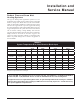
WATER TREATMENT
In hard water areas, water treatment should be used to reduce
the introduction of minerals to the system. Minerals in the
water can collect in the heat exchanger tubes and cause noise
on operation. Excessive build up of minerals in the heat
exchanger can cause a non-warrantable failure.
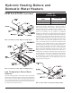
Terminal Strip Connection Options
The scenarios shown in FIG. 42 represent typical terminal
strip connection requirements. The terminal strips are located
on the left side of the unit under the electrical access panel.
Other applications may be accommodated, but must be
addressed individually.
FIG. 42-A shows the position of jumpers as shipped from the
factory for stand-alone operation of boilers or water heaters
(Modes 1 or 2). NOTE: Boilers equipped with the Indoor/
Outdoor Air Reset option should have the 3C-3NO jumper
removed for proper operation.
FIG. 42-B shows connections to the terminal strip for Remote
ON/OFF control of the boiler or water heater (Modes 1 or
2). The 1C-1NO jumper must be removed when making
these wiring connections. This remote ON/OFF control will
provide an Enable/Disable signal to the unit and allow the
unit to operate based on the stage set points, until the remote
ON/OFF signal is cancelled. NOTE: Remote ON/OFF
control in Mode 3 requires the field addition of a jumper
wire from 1NO to 3NO (the 3C-3NO jumper must also be
removed).
FIG. 42-C shows the connections on a boiler equipped with
the I/O Air Reset option only (Mode 1) to accomplish a
Domestic Hot Water (DHW) Priority Override or an Outdoor
Air Lockout Override. This operation is not possible with
Modes 2 or 3. The value of BOIL DSGN should be adjusted to
a temperature setting that will satisfy the DHW requirements
when the Priority Override or O.A. Lockout Override is
activated. This figure also shows the optional Remote ON/
OFF control which can be accomplished in addition to the
DHW Priority Override or O.A. Lockout Override.
FIG. 42-D shows the connections necessary to operate the unit
as a 2-Stage (High/Low Fire) boiler or water heater from an
Energy Management System (EMS). The electronic control
MUST be set to Mode 3 for this to properly operate. The value
of BOIL MAX should be adjusted to a level that will function
as a high temperature stop. The actual set point temperatures
are controlled by the EMS.
FIG. 42-E shows the connections necessary to operate the
unit as a 4-Stage boiler or water heater from an EMS. The
electronic control MUST be set to Mode 3 for this to properly
operate. The value of BOIL MAX should be adjusted to a level
that will function as a high temperature stop. The actual set
point temperatures are controlled by the EMS.
FIG. 42-F shows the Continuous and Intermittent terminals.
External safety devices connected to these terminals will
function to protect the unit. Devices connected to the
Intermittent terminals (B1 and B2) are monitored only when
there is an active Call for Heat. Devices connected to the
Continuous terminals (A1 and A2) are monitored continuously
and will activate an alarm (if the unit is equipped with the
alarm option) any time the safety device senses an abnormal
condition. An additional wire may be field installed from these
safety devices to terminals A3 or B3 (as appropriate) to activate
an alarm (if the unit is equipped with the alarm option).
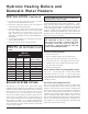
FIG. 42 Terminal Strip (A - F) Connection Options
Figure 42A
Remove Jumper for I/O
Reset Operation
CONTINUOUS
1C 1NO 2C 2NO 3C 3NO 4C 4NO
A1 A2 A3 B1 B2 B3
INTERMITTENT
STAGE 4STAGE 1
HeatDem1
STAGE 2 STAGE 3
HeatDem2
STAND ALONE OPERATION