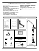
How to Install, operate and maintain your Reverse Osmosis Drinking Water System If you have any questions or concerns when installing, operating or maintaining your reverse osmosis system, call our toll free number: 1-800-972-0135 Monday- Friday, 7 AM - 6 PM CST (in Canada please call 1-800-796-6784) or visit www.northstarconditioning.com When you call, please be prepared to provide the model, date code and serial number of your product, found on the rating decal, located inside the cover.
TABLE OF CONTENTS Page Warranty . . . . . . . . . . . . . . . . . . . . . . . . . . . . . . . . . . . . . . . . . . . . . . . . . . . . . . . . . . . . . . . . . . . . . . . . . . . . . . . . . . 3 Specifications & Dimensions . . . . . . . . . . . . . . . . . . . . . . . . . . . . . . . . . . . . . . . . . . . . . . . . . . . . . . . . . . . . . . . . . . . 4 Unpack and Check Shipment . . . . . . . . . . . . . . . . . . . . . . . . . . . . . . . . . . . . . . . . . . . . . . . . . . . . . . . . . . . . . .
Warranty ONE YEAR LIMITED WARRANTY ON REVERSE OSMOSIS DRINKING WATER SYSTEM (Except filter cartridges and R.O. membrane) Warrantor: North Star Water Conditioning, 1890 Woodlane Drive, Woodbury, MN 55125 Warrantor guarantees, to the original owner, that the Reverse Osmosis Drinking Water System, when installed and maintained in accordance with the instructions, will be free from defects in materials and workmanship for a period of one (1) year from the date of purchase.
Specifications & Dimensions Supply water pressure limits . . . . . . . . . . . . . . . . . . . . . . . . . . . . . . . . . . . . . . . . . . . . . . 40-100 psi (280-689 kPa) Supply water temperature limits . . . . . . . . . . . . . . . . . . . . . . . . . . . . . . . . . . . . . . . . . . . . . 40-100 °F (4.5-37.7°C) Maximum total dissolved solids (TDS) . . . . . . . . . . . . . . . . . . . . . . . . . . . . . . . . . . . . . . . . . . . . . . . . . . 2000 ppm Maximum water hardness @ 6.9 pH . . . . . . . .
Unpack and Check Your Carton INSPECT SHIPMENT NOTE: Codes in the state of Massachusetts require installation by a licensed plumber and do not permit the use of saddle valves. Your Reverse Osmosis Drinking Water System is shipped complete in one carton. Remove all items from your shipping carton. If you live in the state of Massachusetts, review plumbing code 248-CMR of the Commonwealth of Massachusetts before proceeding with the installation. Check all items against the packing list below.
Plan Your Installation PLAN YOUR INSTALLATION TOOLS NEEDED Read through the entire manual before beginning your installation. Follow all steps exactly. Reading this manual will also help you get all the benefits from your system. Your Reverse Osmosis Drinking Water System can be installed under a sink or in a remote location. Typical remote sites are a laundry room or utility room. Review the location options below and determine where you are going to install your system.
Plan Your Installation All install parts included in package. Drain Adapter for Reverse Osmosis Waste Water Tee Feed Adaptor Cold Water Supply HOT Reverse Osmosis Assembly COLD Storage Tank Sink Drain P-Trap Shutoff Valve Typical Under Sink Installation Outside Faucet (Hard Water) Soft, Cold Water Hard W ater Lin e Soft, Hot Water Outside Faucet (Hard Water) Soft water to Reverse Osmosis System Shutoff Valve Water Heater Water Meter Air Gap (see p.
Overview and Site Preparation OVERVIEW Read through the entire manual before beginning your installation. There are seven steps to installing your Drinking Water system. They are as follows: STEP A - Install Cold Water Supply fitting STEP B - Install Drain Adapter STEP C - Install Reverse Osmosis Assembly STEP D - Install Storage Tank STEP E - Install Reverse Osmosis Faucet STEP F - Connect Tubing STEP G - Sanitize, Pressure Test, Purge System These steps are explained in detail over the next few pages.
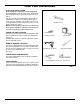
Step A - Install Supply Water Fitting Check and comply with local plumbing codes as you plan, then install a cold feed (supply) water fitting. Refer to the Specifications page for supply water requirements. The fitting must provide a leak-tight connection to the RO 1/4" tubing. A typical connection using the included water supply fitting is shown in Figure 7. NOTE: Local code may dictate which type of water fitting is used. Consult a plumber if you are not familiar with local codes or plumbing procedures.
Step B - Install RO Drain Under Sink INTRODUCTION Single trap A suitable drain point is needed for the drain water from the Reverse Osmosis Filter. You have two options to choose from: • Install the Drain Adapter included with your unit See Fig 8, Fig. 9, and Fig. 10. This is used in under the sink installations. The drain adapter kit is installed onto your sink drain pipe above the P-trap. See Fig. 8. • Use another existing drain in your home (See Fig 11, Fig.
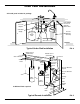
Step B - Install RO Drain In Remote Location Outside Faucet (Hard Water) Soft, Cold Water Hard W ater Lin e Soft, Hot Water Outside Faucet (Hard Water) Soft water to Reverse Osmosis System Shutoff Valve Remote Location Installation Water Softener Sump 1-1/2” Air Gap 1-1/2” Air Gap Stand pipe 1-1/2” Air Gap Floor Drain INSTALL A REMOTE DRAIN POINT Storage Tank Main Shutoff Valve FIG.
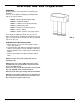
Step C: Install RO Filter Assembly INSTALL REVERSE OSMOSIS FILTER ASSEMBLY Hanger Washer (2) The Reverse Osmosis Filter Assembly is mounted on hanger washers. Screw (2) 9'' See Fig 13. The hanger washers allow you to lift the filter assembly from the washers without any hardware removal. When planning your installation, you need to leave room for changing filters. Complete the following steps to install your Reverse Osmosis Filter Assembly: 15-1/2'' minimum up from floor.
Step D - Install Storage Tank The fitting on the supply tank may need to be tightened 7-8 full turns to get a good seal. Do not overtighten. INSTALL STORAGE TANK Tank Nipple 1. Apply of thread sealing tape (2 wraps clockwise) to the threads on the nipple at the top of the tank. See Fig 14. Tubing Connector 2. Locate the tubing connector. See Fig. 14. Tighten the tubing connector onto the tank nipple 7-8 full turns, being careful not to cross thread or overtighten. 3.
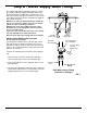
Step E: Install RO Faucet SELECT LOCATION OF REVERSE OSMOSIS FAUCET MOUNTING HOLE You will need to select the location of the Reverse Osmosis Faucet. You have three options to choose from: • Use the existing sink top hole for the spray hose or soap dispenser (Must be 1-1/4” in diameter) • Drill a new hole in the sink • Drill a new hole in the countertop next to the sink 1. Determine where you are going to install your Reverse Osmosis Faucet. 2.
Step E: Install RO Faucet (cont.) INSTALL REVERSE OSMOSIS FAUCET 1. Locate and organize your RO faucet install parts. Refer to Fig. 16. 2. Snap the o-ring into the groove on the bottom of the ring and slide the monitor ring onto the faucet stud. The monitor ring LED wire must be routed through the sink or countertop hole and through the spacer, if used. See Fig. 16. Faucet 3. Locate the 3/8" black tubing and push one end onto the 3/8" faucet barb fitting, see Fig. 17. 4.
Step F - Connect Tubes HOW TO CUT AND CONNECT THE TUBES Your Reverse Osmosis system includes push-in fittings for quick tubing connection. Review the following instructions before connecting the tubes in the next step. Failure to follow these instructions may lead to future leaks. Foam Plug Cut tubes to length 1. Use a sharp cutter or knife to cut the end of tubing. Always cut the tubing square. See Fig. 19. 2.
Step F - Connect Tubes (cont.) 3/8” BLACK Tubing BL UE 1/4” GREEN Sink P–Trap ” 3/8 HOT COLD Drain Adaptor 1/4” RED Tee Feed Adaptor NOTE: Tubing lengths should allow for the removal of the assembly from the hanger washers for servicing. If tubing lengths are shortened for neater appearance, it may be necessary to keep the assembly on the hanger washers for service. NOTE: Codes in the state of Massachusetts require installation by a licensed plumber and do not permit the use of saddle valves.
Step G - Sanitize, Test and Purge System SANITIZE THE SYSTEM Sanitizing is recommended immediately after installation of the Reverse Osmosis system. It’s also recommended after servicing inner parts. It is important that the person installing or servicing the system have clean hands while handling inner parts of the system. Complete the following steps to sanitize the system. See Fig. 25. 1. Make sure that the water supply to the Reverse Osmosis system is off. 2. Open the Reverse Osmosis faucet.
Step G - Sanitize, Test and Purge System (cont.) PRESSURE TEST THE SYSTEM NOTE: Complete the sanitizing procedures on the preceding page before pressure testing. Kitchen Faucet To pressure test the system, complete the following steps. 1. Open the water supply valve to the Reverse Osmosis system. 2. Purge air from the house plumbing by opening several house faucets. Close faucets when water runs smooth, with no spurting. 3. Pressure will start to build in the RO system.
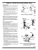
How Your RO Water System Works INTRODUCTION: Your Reverse Osmosis (RO) Drinking Water System uses your household water pressure to force water through three filters. Minerals and impurities are filtered out. Delicious tasting drinking water goes to the storage tank-ready for your use. Minerals and impurities are sent down the drain. The following paragraphs will explain in detail how your Reverse Osmosis Drinking Water System works. Battery PREFILTER: Water from the cold supply pipe enters the prefilter.
How Your RO Water System Works PRODUCT WATER FAUCET BL AC K Air Gap PRODUCT WATER Gravity Drain DRAIN WATER AUTOMATIC SHUTOFF WATER IN 6 Drain Flow Control Check Valve 8 BLUE GREEN 1 POSTFITLER PREFILTER 5 RO MEMBRANE RED 2 7 3 PRODUCT WATER STORAGE YELLOW Reverse Osmosis Water Flow Schematic Water Flow Description 1. 2. 3. 4. 5. 6. 7. 8. Water enters prefilter. Sand, silt and other sediments are reduced. Chlorine is also reduced. See Fig. 28.
Maintenance PREFILTER/POSTFILTER MAINTENANCE NOTE: It is recommended to replace the battery, prefilter and postfilter cartridges at least every 6 months of product water use. Replace more often if they begin to plug with sediment. The prefilter and postfilter are replaceable sediment cartridges with activated carbon in their composition. See Fig. 29. You must periodically replace the prefilter and postfilter cartridge. This will protect the RO membrane from being destroyed by chlorine.
Maintenance FLOW CONTROL The flow control is required for proper operation of the Reverse Osmosis system. See Fig. 30. The flow control, located inside the push-in elbow fitting on the drain port of the system housing, keeps water flowing through the membrane at the required rate. This ensures that the system produces the best quality product water. Flow Control Insert Push-in Elbow Fitting 1/4” Red Tubing Periodically check the flow control to be sure the small hole through it is clean and unrestricted.
Troubleshooting Problem: Chlorine taste and/or odor in the RO product water. Cause: The level of chlorine in your water supply Correction: exceeds maximum limits, and has destroyed the Reverse Osmosis membrane. Cause: The prefilter is no longer removing chlo- Correction: rine from the water supply. Problem: Other taste and/or odor. Cause: Postfilter expended. Cause: Reverse Osmosis membrane cartridge expended. Correction: Cause: Contamination in product water storage tank.
Troubleshooting Problem: Water leaking from faucet airgap hole. Cause: Drain side of faucet airgap (3/8” black tubing) plugged, restricted or incorrectly connected to drain point. Correction: Cause: Tubing not cut square. Correction: Cut tubing square. See pages 16 & 17. Cause: Tubing nicked. Correction: Remove tube from connection. Remove nicked portion by cutting tube to shorter length. Reinsert in connection. See pages 16 & 17.
Exploded View 1 28 2 3 6 4 7 5 8 9 6 10 11 12 15 13 14 27 17 18 19 26 1/4” red tubing 25 21 20 24 23 22 26 16
Parts List Key No. Part No. Description – 7333145 1 á Automatic Shutoff Kit (incl. Key No. 3, 4 of Key No. 2 & 6 of Key No. 1) 3 á 2 á – 7333137 4 á – 7333179 6 á 8 á 5 7 á á – 7333195 9 á ¢ á 10 7280156 – 7333200 11 á 13 á 12 14 á á Screw (6 req’d) Washer (4 req’d) Automatic Shutoff Cover Assembly Key No. Part No. 15 7296521 – 7333129 16 á – 7333153 18 á 20 7287506 21 7287514 23 7208489 17 Check Valve Kit (includes Key No. 4 & 2 of Key No.
- PARTS RETURN TAGS If you have a defective part or assembly under warranty, please fill in a parts return tag. Cut out the tag and include it with the defective part when you return it to the place where you purchased the unit. PARTS RETURN TAG PARTS RETURN TAG CUSTOMER’S NAME CUSTOMER’S NAME STREET ADDRESS STREET ADDRESS CITY ZIP CODE STATE CITY ZIP CODE STATE R.O. MODEL NUMBER SERIAL NUMBER R.O.