COMPLETE RAIL-LESS RACKING SYSTEM INSTALLATION GUIDE REVISION DATE: 06/28/22 VERSION: v2.9 ECOFASTENSOLAR.
REVISION DATE: 06/28/22 VERSION: v2.
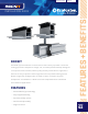
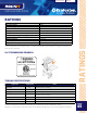
REVISION DATE: 06/28/22 VERSION: v2.9 ROCKIT The RockIt system conforms to UL 2703 and is the industry’s premier rail-less PV racking system for composition shingle, tile, and metal pitched rooftops. Designed in conjunction with installers, RockIt quickly & easily installs with a single tool. It features an easy-to-position mount alignment and a top-down leveling system. RockIt is logistically intelligent with no need to ship or transport long rails.
REVISION DATE: 06/28/22 VERSION: v2.
REVISION DATE: 06/28/22 VERSION: v2.
REVISION DATE: 06/28/22 VERSION: v2.9 INSTALLATION GUIDE RATINGS Fire Ratings* Class A System Fire Rating Max System Voltage 1500V Max Fuse Rating 40A Certification Conforms to UL STD 2703 Markings Product listing label is located on RockIt Mount Roof Pitch 2:12 - 21:12 UL 2703 Allowable Design Load Rating 30 psf downward, 30 psf upward and 20 psf lateral Max Module Size 24 sq. ft.
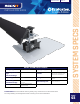
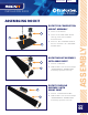
REVISION DATE: 06/28/22 VERSION: v2.9 INSTALLATION GUIDE ASSEMBLING ROCKIT ROCKIT FOR COMPOSITION MOUNT ASSEMBLY 2 3 1 1. 2011012 - RI MOUNT 2. 2011013 - RI COMP SLIDE AL BLK with lag screw & 5/16" EPDM bonded washer 3. 3012010 - GF1 FLASHING GLV BLK 8X12" or 3012020 - GF-1 FLASHING GLV BLK 8X10" ROCKIT MOUNT ASSEMBLY WITH ARRAY SKIRT 1. 2011012 - RI MOUNT 2 2.
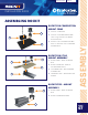
REVISION DATE: 06/28/22 VERSION: v2.9 INSTALLATION GUIDE ASSEMBLING ROCKIT ROCKIT FOR COMPOSITION MOUNT COMP 1. 2011012 - RI MOUNT 1 2. 2011013 - RI COMP SLIDE AL BLK with 4” lag screw & 5/16” EPDM bonded washer 2 3 ROCKIT FOR S TILE MOUNT ASSEMBLY 1 1. 2 ROCK-IT MNT - ROCK-IT MOUNT BLK 2. ROCK-IT SLIDETILE - ROCK-IT SYSTEM SLIDE TILE 8" 3 3. TF-S SIERRA TAN - TILE FLASHING S-SIERRA TAN 4. TILE BASE-S LITE - TILE BASE-S LITE ASSEM 4 ROCKIT STEEL - MOUNT ASSEMBLY 1 1. ASSEMBLY 3.
REVISION DATE: 06/28/22 VERSION: v2.9 INSTALLATION GUIDE MODULE SPACING N N N STRUCTURAL ATTACHMENT POINTS • Find the required structural attachment points. S S S Max 48’ Max 72’ • Spacing may vary depending upon project specific structural requirements: i.e. high snow and wind load areas may require lesser bracket spacing in the E-W axis vs. the maximum spacing. • Max spacing is 48" OC for portrait orientation and 72" OC for landscape orientation.
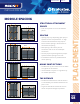
REVISION DATE: 06/28/22 VERSION: v2.9 INSTALLATION GUIDE MOUNT PLACEMENT STAGGERED LAYOUT WITH STAGGERED MOUNTING POINTS • The array layout instructions in this installation manual offer a general due to a variety of factors (roof obstacles, shading, etc.) other layouts are required. RockIt Mount RockIt Coupling Cantilever CANTILEVER & OFFSET • Cantilever: Maximum cantilever is 1/3 bracket spacing. For portrait orientation installations, check layout prior to installing.
REVISION DATE: 06/28/22 VERSION: v2.9 INSTALLATION GUIDE FLASHING & SLIDE INSTALLATION 1 1 SNAP LINES Locate the rafters and snap horizontal lines to mark the installation position for each GF-1 flashing. 2 PILOT HOLE member for the lag screw. Backfill with sealant compatible with the roof type.
REVISION DATE: 06/28/22 VERSION: v2.9 INSTALLATION GUIDE SYSTEM INSTALLATION 1 INSTALL ECOFASTEN FLASHING WITH ROCKIT MOUNTS • Follow EcoFasten installation instructions for flashings and brackets. • Optimum vertical distance between lag bolts is 1 5/16" plus module dimension. • Set mounts on eave most row so that the RockIt pedestal is on the South end of RockIt slide. • Set mounts on all upper rows to the North end of RockIt slides.
REVISION DATE: 06/28/22 VERSION: v2.9 INSTALLATION GUIDE SYSTEM INSTALLATION 5 5 INSTALL ROCKIT COUPLINGS AND ARRAY SKIRT • On eave row only, slide RockIt array skirt onto RockIt coupling shelf. 6 ALIGN & STRAIGHTEN 1ST ROW WITH ROCKIT ARRAY SKIRT • Refer back to pg. 7, prior to starting this step. • Use North-South adjustment of the RockIt Pedestal to 6 straighten RockIt array skirt. • Torque screw on side of RockIt pedestal to 150 in-lbs to secure it to the RockIt slide.
REVISION DATE: 06/28/22 VERSION: v2.9 INSTALLATION GUIDE SYSTEM INSTALLATION 9 9 INSTALL 2ND ROW OF ROCKIT ROCKIT MOUNTS & COUPLINGS Install RockIt couplings on the upslope side of 1st 10 INSTALL 2ND ROW OF ROCKIT MOUNTS Torque 2nd row of mid clamps on RockIt mounts and RockIt couplings to 200 in-lb. 10 11 INSTALL THE REMAINDER OF THE PV COMPONENTS Install balance of PV modules, ensuring that the RockIt pedestals are in the appropriate position, then torque mid clamps to secure modules.
REVISION DATE: 06/28/22 VERSION: v2.9 INSTALLATION GUIDE ROCKIT TILE INSTALLATION 1 TILE MOUNTING SYSTEM INSTALLATION 1. Locate rafter in the typical manner. Remove tile. 2. Pre-drill lag bolt holes through base and butyl 3. Remove release paper from bottom of butyl tape. 2 • Place base in proper location and press down firmly. • Backfill holes with sealant. Install lag bolts in predrilled locations. 4. Install Flashing.
REVISION DATE: 06/28/22 VERSION: v2.9 INSTALLATION GUIDE ROCKIT STEEL INSTALLATION 1 1 EAST-WEST ROOF MARKING Snap horizontal lines to mark the installation position for each Rockit 2 ROOF MARKING Mark the center of the corrugation and draw a straight line to indicate where the 2 mounting profile must be installed. Double check the ridge width (minimum of 0.75") and metal thickness (26ga). 3 ATTACH MOUNTING PROFILES Screw the mounting profiles onto the roof using the self piercing screws.
REVISION DATE: 06/28/22 VERSION: v2.9 INSTALLATION GUIDE STANDING SEAM ROCKIT INSTALLATION 1 1 EAST-WEST ROOF MARKING Snap horizontal lines to mark the installation position for each Rockit 2 SIMPLEBLOCK Place the SimpleBlock over the seam so that the North side of the block is aligned with the snapped horizontal lines. Lift up on the 2 SimpleBlock until the lip contacts the seam in the fold. Torque the two set screws to 150 in-lbs using a 3/16" hex drive.
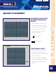
REVISION DATE: 06/28/22 VERSION: v2.9 INSTALLATION GUIDE STANDING SEAM ROCKIT INSTALLATION 4 4 COMP SLIDE Place the RockIt comp slide over the bolt with the long side of the comp slide facing upslope towards the eve of the SimpleBlock and place the 5/16" flange nut over the bolt tip and torque to 150 in-lbs. 5 5 MOUNT PLACEMENT When installing the RockIt mount along the comp slide, it cannot be placed anywhere within the last 1" of the comp slide as shown in red.
REVISION DATE: 06/28/22 VERSION: v2.9 INSTALLATION GUIDE CONDUIT MOUNT INSTALL 1 1 INSERT FLASHING Select the appropriate position for the condiut mount and slide flashing up under the shingles. INSERT LAG BOLT With the EPDM bonded washer threaded onto the lag bolt followed by the Conduit Mount Comp Bracket and then insert the lag bolt into the 2 gasketed hole in the flashing. The bracket can be rotated for orientation in any direction.
REVISION DATE: 06/28/22 VERSION: v2.9 INSTALLATION GUIDE TILE CONDUIT MOUNT INSTALL 1 1 INSERT MOUNT Lift up the tile above which overlaps the Tile you want to run conduit across and slide the hook end of the Conduit Mount Tile under the tile and hook it 2 REPLACE TILE Replace the top tile, taking care that it properly 2 interconnects with adjacent tiles. The weight of the tile will hold the Conduit Mount Tile in place.
REVISION DATE: 06/28/22 VERSION: v2.9 INSTALLATION GUIDE INSTALL FRAME MLPE MOUNT ACCESSORY • Slide the Frame MLPE Mount into the slot of the micro-inverter/power optimizer. • Slide the micro-inverter/optimizer flange underneath the inside of the module frame with the frame MLPE mount on the outside of the frame. • Tighten the bolt to 144 in-lb to clamp the Frame MLPE Mount to the module frame and the microinverter/power optimizer to the Frame MLPE Mount.
REVISION DATE: 06/28/22 VERSION: v2.9 INSTALLATION GUIDE JUNCTION BOX INSTALLATION JUNCTION BOX PREP DECK MOUNTED INSTALLATION DECK SCREWS WITH SEALING WASHERS (2X) Align sealing oval of box to align with mating feature on flashing. An EPDM foam gasket is pre-installed to the underside of the junction box to seal the flashing to the box without the need for additional sealant. Secure with supplied #12 x 1- “ deck screws (2x) until the junction box is pulled tight to the flashing.
REVISION DATE: 06/28/22 VERSION: v2.9 INSTALLATION GUIDE BONDING AND GROUNDING THERMAL EXPANSION & BONDING • A thermal expansion gap is required per each continuous 40' length of modules. in the RockIt array skirt and also between the modules at that point.
REVISION DATE: 06/28/22 VERSION: v2.9 INSTALLATION GUIDE BONDING AND GROUNDING NECESSARY COMPONENTS One of the following grounding lugs (or any UL 2703 Compliant ground Lug): • Burndy CL50-1TN Ground Lug (UL2703 - E3514343 / UL 467 E9999) E354420/ UL 467 - E34440) • ILSCO GBL-4DBT (UL2703 E354420 / UL 467 - E34440) • ILSCO GBL-4DBTH (UL2703 E354420 / UL 467 - E34440) • ILSCO GBL-4SS (UL2703 - E354420 / UL 467 - E34440) INSTALLATION • Insert the flange bolt into the module ground hole.
REVISION DATE: 06/28/22 VERSION: v2.9 INSTALLATION GUIDE UL 2703 CERTIFIED MODULES This racking system may be used to ground and/or mount a PV module complying with UL 1703 or UL 61730 only when the specific module has been evaluated for grounding and/or mounting in compliance with the included instructions. Unless otherwise noted, “xxx” refers to the module power rating and both black and silver frames are included in the certification.
REVISION DATE: 06/28/22 VERSION: v2.
REVISION DATE: 06/28/22 VERSION: v2.
REVISION DATE: 06/28/22 VERSION: v2.
REVISION DATE: 06/28/22 VERSION: v2.
REVISION DATE: 06/28/22 VERSION: v2.9 INSTALLATION GUIDE MANUFACTURER LIST OF UL 2703 APPROVED MODULES Trina modules with 30 and 35 mm frames TSM-xxxYYZZ Trina “YY” can be DD05, DD05A, DD06, DE05, DE09, DX05A, DE06X, PA05, PC05, PD05, PE14 or PX05; and “ZZ” can be blank or A, .05, .05(II), .08, A.05, A.08, A(II), A.05(II), A.08(II), C.05, C.07, C.05(II), C.07(II), H, H.05, H.08, H.05(II), H.