
Operating instructions

4
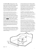
The purge pump can be used to pressurize the system to
an initial static pressure of 30 to 40 psi. Make sure the
system is at this pressure after the loop pipe has had
enough time to stretch. In order to achieve the 30 to 40
psi initial pressure, the loop may need to be pressurized to
60 to 65 psi. This static pressure will fluctuate from
heating to cooling season, but the pressure should always
remain above zero so circulation pumps do not cavitate
and air cannot be pulled into the system. For
information regarding earth loop installations contact your
local installer, distributor or factory representative.
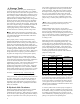
Table 1 – Loop Side Flow Rates
Model Closed Loop Open Loop
Flow dP Flow dP
(gpm) (psi) (gpm) (psi)
GW29
7 4.0 4 1.5
GW36
8 5.5 4 1.5
GW42
10 7.8 5 1.7
GW52
11 5.2 6 1.6
GW59
13 17.0 8 5.6
GW67
14 7.0 10 3.8
GW98
22 3.8 14 2.7
GW120
26 4.5 16 3.0
GW380
78 8.3 N/A
B. Open Loop Applications
An open system gets its name from the open discharge of
water after it has been used by the heat pump. A well
must be available that can supply all of the water
requirements (see Table 1) of the heat pump along with
any other water requirements drawing off that same well.
The well must be capable of supplying the heat pump’s
required flow rate for up to 24 hours per day on the
coldest winter day.
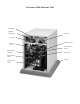
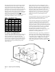
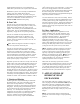
Figure 2 – Open Loop Water Plumbing
Figure 2 shows the necessary components for water
piping of an open system. First, a bladder type pressure
tank with a "draw down" of at least 1½ times the well
pump capacity must be installed on the supply side of the
heat pump. Shut off valves and boiler drains on the
entering and leaving water lines are necessary for future
maintenance issues. A screen strainer is placed on the
supply line with a mesh size of 40 or 60 and enough
surface area to allow for particle buildup between
cleanings.
Pressure/Temperature (P/T) ports are placed in the supply
and discharge lines so that thermometers or pressure
gauges can be inserted into the water stream.
On the well water discharge side of the heat pump, a flow
control valve must be mounted next to the heat pump to
regulate the maximum water flow through the unit. A
solenoid valve is then installed and wired to the accessory
plug on the controller. This valve will open when the unit
is running and close when the unit stops. A visual flow
meter is then installed to allow visual inspection of the
flow requirements. The flow meter is useful in
determining when maintenance is required. (If you can't
read the flow, cleaning is required. See Water Coil
Maintenance for cleaning instructions.)
Schedule 40 PVC piping, copper tubing, polyethylene or
rubber hose can be used for supply and discharge water
lines. Make sure line sizes are large enough to supply the
required flow with a reasonable pressure drop (generally
1" diameter minimum). NOTE: Do not use plastic
female fittings with metal male fittings, or fractures may
result in the female fittings. Always use plastic male into
steel female!