
Technical data

Installation, Operation, And Service Instructions 9
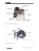
• Burner Motor: (figure3) Multitask motor turns the burner blower and integrated air
compressor.
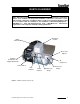
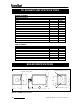
• Air Pressure Adjuster: (figure1) Adjusts the air pressure going to the pre-heater block.
Should be adjusted between 12 PSI and 13PSI as indicated on the Air Pressure Gauge
on the burner for thorough burn of the waste oil.
Note: In order to insure proper air adjustment, air gauge must read 0 when burner
is cycled off or powered down.
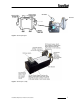
• Oil Pressure Gauge: (figure 1) Displays oil pressure at the burner. Adjust flame length
in the heater combustion chamber viewed through the inspection port located directly
above the burner gun assembly by increasing CW or decreasing CCW the adjuster
located on the oil delivery pump (figure 5). The adjuster increases or decreases the
pump motors RPM which increases or decreases the delivery of fuel to the burner. When
you increase or decrease the fuel to the burner you will notice the flame length will
increase or decrease. Adjust flame length so flame is just slightly less than halfway
down main combustion chamber tube.
IMPORTANT:
Once adjusted for correct flame length, take note of oil gauge setting for bench mark
pressure reading needed when burning the specific fuel mixture generated by the owner.
PLEASE NOTE- Once flame is set the oil pressure gauge can read various pressures
when different viscosities of oils are used. The oil pressure gauge is an indicator of
where the PSI reading will be when that oil viscosity is being burned. The oil gauge is
used for servicing diagnostics assistance.
• Power Indicator: (figure1) Indicates when power is present at the burner.
• Run Indicator: (figure1) Indicates that the burner is ready for operation after the initial
pre-heat time of approx. 5 minutes from initial power up.
• Power Switch: (figure1) Switches power off and on to the burner.