EP27 EP30 EP34 EP40 How to install, operate and maintain your Demand Controlled Water Softener Do not return water softener to store If you have any questions or concerns when installing, operating or maintaining your water softener, call our toll free number: 1-800-693-1138 Monday- Friday, 7 AM - 6 PM CST or visit www.ecopurewaterproducts.com When you call, please be prepared to provide the model and serial number of your product, found on the rating decal, located on the rim below the salt lid hinges.
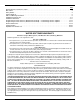
TABLE OF CONTENTS Page Specifications & Performance Claims . . . . . . . . . . . . . . . . . . . . . . . . . . . . . . . . . . . . . . . . . . . . . . . . . . . . . . . . . . . . 3 Dimensions . . . . . . . . . . . . . . . . . . . . . . . . . . . . . . . . . . . . . . . . . . . . . . . . . . . . . . . . . . . . . . . . . . . . . . . . . . . . . . . . 4 Safety Guides . . . . . . . . . . . . . . . . . . . . . . . . . . . . . . . . . . . . . . . . . . . . . . . . . . . . . . . . . . . . . . . . . . . . . . . .
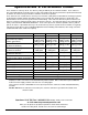
Specifications & Performance Claims These models are efficiency rated. The efficiency rating is valid only at the minimum salt dose. These softeners have a demand initiated regeneration (D.I.R.) feature that complies with specific performance specifications intended to minimize the amount of regenerant brine and water used in their operation.
Dimensions 52.4 cm IN 8.6 cm 43.8 cm OUT TOP VIEW IN - OUT 108.6 cm 94.0 cm FRONT VIEW SIDE VIEW FIG. 1 Safety Guides = The water softener requires a minimum water flow of 3 gallons (11.4 L) per minute at the inlet. Maximum allowable inlet water pressure is 100 psi (7.0 kg/cm2). If your house water pressure is over the maximum, install a pressure reducing valve in the water supply pipe to the softener (Adding a pressure reducing valve may reduce the flow).
Inspect Shipment Remove and discard (or recycle) all packing materials. To avoid loss of small parts, we suggest you keep the small parts in the parts bag until you are ready to use them. The parts required to assemble and install the water softener are included with the unit. Thoroughly check the water softener for possible shipping damage and parts loss. Also inspect and note any damage to the shipping carton.
Installation Requirements LOCATION REQUIREMENTS PLUMBING CODES Consider all of the following when selecting an installation location for the water softener. All plumbing must be completed in accordance with national, state and local plumbing codes. = Do not locate the water softener where freezing temperatures occur. Do not attempt to treat water over 49ºC. Freezing temperatures or hot water damage voids the warranty. AIR GAP REQUIREMENTS A drain is needed for regeneration water (See Figure 3).
Installation Requirements VALVE DRAIN REQUIREMENTS 1/4” NPT Thread Barbs for 9.5 mm I.D. Tubing Using the flexible drain hose (included), measure and cut to the length needed. Flexible drain hose is not allowed in all localities (check your plumbing codes). If local codes do not allow use of a flexible drain hose, a rigid valve drain run must be used. Purchase a compression fitting (1/4 NPT x 1.25 cm minimum tube) and 1.25 cm tubing from your local hardware store.
Installation Instructions TYPICAL INSTALLATION To Outside Faucets Hard Water r Pipe Main Wate Conditioned Water Pipe Clips Water Softener Valve Plug-in Transformer 1” NPT Threaded Adaptor Outlet To Controller O-ring Inlet Overflow Drain Elbow Valve Drain Elbow Salt Storage Tank Overflow Hose* Valve Drain Hose* *Do not connect the water softener valve drain hose to the salt storage tank overflow hose.
Installation Instructions continued from previous page Top Cover 2. Visually check and remove any debris from the water softener valve inlet and outlet ports. Nozzle & Venturi Assembly Salt Lid 3. Make sure the turbine assembly spins freely in the "out" port of the valve (See Figure 10). Brine Tank Overflow Grommet Brinewell Cover 4. If not already done, put a light coating of silicone grease on the single bypass valve o-rings. 5.
Installation Instructions COLD WATER PIPE GROUNDING INSTALL SALT STORAGE TANK OVERFLOW HOSE CAUTION: The house cold water pipe (metal only) is often used as a ground for the house electrical system, The 3-valve bypass type of installation, shown in Figure 8, will maintain ground continuity. If you use a plastic bypass valve at the unit, continuity is broken. To restore the ground, do the following: 1. Measure, cut to needed length and connect the 9.
Installation Instructions 2. Complete the programming steps on: Pages 12 & 13 for Models EP27 & EP30, or Pages 15 & 16 for Models EP34 & EP40. If removing clips... SANITIZE THE WATER SOFTENER / SANITIZE AFTER SERVICE Care is taken at the factory to keep your unit clean and sanitary. Materials used to make the unit will not infect or contaminate your water supply, and will not cause bacteria to form or grow. However, during shipping, storage, installation and operation, bacteria could get into the unit.
Programming the Water Softener (Models EP27 & EP30) UP button Display DOWN button RECHARGE button SELECT button FIG. 17 SET WATER HARDNESS NUMBER When the transformer is plugged into the electrical outlet, a model code and a test number (example: J2.0), begin to flash in the faceplate display. Then, “12:00 PM” and the words “PRESENT TIME" begin to flash. 1. Press the SELECT button once again to display a flashing “25” and the word “HARDNESS”.
Programming the Water Softener (Models EP27 & EP30) SET RECHARGE (REGENERATION) TIME SET SALT EFFICIENCY Your demand water softener will automatically regenerate when it needs to, based on water usage. The time of day that the automatic recharge cycle begins may be changed as follows: When this feature is ON, the water softener will operate at salt efficiencies of 4000 grains of hardness per pound of salt or higher (May recharge more often using smaller salt dosage but more regeneration water).
Customizing Features / Options (Models EP27 & EP30) RECHARGE NOW ADJUSTABLE BACKWASH At times of greater than normal water use, such as when you have guests, you could run out of conditioned water before the next scheduled recharge. If this happens, you may want to initiate an immediate regeneration, as follows: If your incoming water supply has higher sediments or clear water iron, a longer Backwash and/or Fast Rinse time may help in keeping the unit cleaner. To change the length of the Backwash: 1.
Programming the Water Softener (Models EP34 & EP40) Low Salt LED Indicator Display UP button RECHARGE button SELECT button DOWN button FIG. 29 SET WATER HARDNESS NUMBER When the transformer is plugged into the electrical outlet, a model code and a test number (example: J2.0), begin to flash in the faceplate display. Then, “12:00 PM” and the words “PRESENT TIME" begin to flash. 1. Press the SELECT button once again to display a flashing “25” and the word “HARDNESS”.
Programming the Water Softener (Models EP34 & EP40) SET RECHARGE (REGENERATION) TIME SET SALT EFFICIENCY Your demand water softener will automatically regenerate when it needs to, based on water usage. The time of day that the automatic recharge cycle begins may be changed as follows: When this feature is ON, the water softener will operate at salt efficiencies of 4000 grains of hardness per pound of salt or higher (May recharge more often using smaller salt dosage but more regeneration water).
Customizing Features / Options (Models EP34 & EP40) RECHARGE NOW ADJUSTABLE BACKWASH At times of greater than normal water use, such as when you have guests, you could run out of conditioned water before the next scheduled recharge. If this happens, you may want to initiate an immediate regeneration, as follows: If your incoming water supply has higher sediments or clear water iron, a longer Backwash and/or Fast Rinse time may help in keeping the unit cleaner. To change the length of the Backwash: 1.
Routine Maintenance Customizing Features / Options ADDING SALT (All Models) Lift the salt lid and check the salt storage level frequently. If the water softener uses all the salt before you refill it, you will experience hard water. Until you have established a refilling routine, check the salt every two or three weeks. Always add if less than 1/4 full. Be sure the brinewell cover is on.
Routine Maintenance CLEANING THE NOZZLE & VENTURI PROTECT THE WATER SOFTENER FROM FREEZING A clean nozzle & venturi (See Figure 42) is a necessity for the water softener to work properly. This small component creates the suction to move brine from the brine tank, into the resin tank. If it should become plugged with sand, silt, dirt, etc., the water softener will not work, and hard water will result. If the softener is installed where it could freeze (summer cottage, lake home, etc.
Troubleshooting Guide PROBLEM No soft water No soft water & display is blank No soft water & salt level not dropping No soft water & salt storage tank full of water, water running to drain while unit is in the soft water cycle CAUSE CORRECTION 1. No salt in the storage tank. Refill with salt and then use RECHARGE NOW feature. 2. Fuse blown, circuit breaker popped, or circuit switched off (See “Power Outage Memory” on Page 18).
Troubleshooting AUTOMATIC ELECTRONIC DIAGNOSTICS letter appears, the switch is closed. If the dash shows, the switch is open. This water softener has a self-diagnostic function for the electrical system (except input power and/or water meter). The water softener monitors electronic components and circuits for correct operation. If a malfunction occurs, an error code appears in the display. Water Meter Switch FIG. 45 4.
Troubleshooting RESETTING TO FACTORY DEFAULTS If water does not enter the tank, look for an obstructed nozzle, venturi, fill flow plug, brine tubing, or brine valve riser pipe. To reset the electronic controller to its factory default for all settings (time, hardness, etc.): 2. After observing fill, press the RECHARGE button to move the softener’s valve into the brine position. A slow flow of water to the drain will begin.
Notes 23
Softener Exploded View 13 14 12 16 Valve Assembly See Pages 26 & 27 for parts 15 1 2 28 11 17 19 4 18 6 3 7 20 8 7 26 21 6 5 5 22 8 10 27 9 23 24 25 24
Softener Parts List Key No. Part No. Description – 7112963 1 á Distributor O-Ring Kit (includes Key Nos. 1-3) 3 á 2 4 5 O-Ring, 20.6 x 27.0 mm á 7077870 7105047 7331177 6 á 7264922 9 0502272 11 7330977 12 13 14 ¢ 17 Top Distributor Repl. Bottom Distributor 18 Tank Neck Clamp Kit (includes Key Nos. 6 & 7) Retainer Clip (2 req.) á 7334696 10 16 O-Ring, 69.9 x 76.2 mm Clamp Section (2 req.) 7114787 8 15 O-Ring, 73.0 x 82.6 mm – 7 Key No.
Valve Exploded View 50 51 70 52 91 53 90 87 56 57 89 86 88 85 59 60 58 61 84 66 83 67 82 70 62 81 63 80 64 76 68 65 78 55 54 79 69 71 77 74 Wear Strip Seal Cross-section View 75 26 73 72
Valve Parts List Key No. 50 Part No. 7338111 Screw, #6-19 x 3.5 cm (2 req.) 7337474 Motor Mount 51 7281291 53 7284964 52 54 7030713 – 7331185 55 á 57 á 56 58 59 á 65 á á á 7092642 7199232 7129889 7337563 71 7278442 72 7337571 – 7113040 73 á 74 á O-Ring, 6.4 x 9.5 mm (2 req.) 80 81 Flow Plug, 7.6 lpm Seal Kit (includes Key Nos. 60-65) 7081201 1202600 7187065 7253808 7081104 7095030 1148800 7187772 O-Ring, 11.1 x 15.