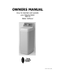
OWNERS MANUAL How to maintain and operate your Miracle Water MW-15 Water Softener Part No.
WARRANTY TEN YEAR LIMITED WARRANTY GENERAL CONDITIONS Damage to any part of this water softener because of misuse, misapplication, neglect, alteration, accident, installation or operation contrary to our printed instructions, or damage caused by any unusual force of nature such as, but not limited to, freezing, flood, hurricane, tornado, or earthquake is not covered by this warranty. In all such cases, regular parts and service charges will apply.
UNPACKING / INSPECTION The softener is shipped in one master carton. The softeners are completely assembled at the factory, except as required at installation. Be sure to check the entire softener for any shipping damage or parts loss. Also note damage to the shipping cartons. Contact the transportation company for all damage and loss claims. The manufacturer is not responsible for damages in transit. Small parts, needed to install the softener, are in a parts bag.
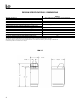
DESIGN SPECIFICATIONS / DIMENSIONS RATED CAPACITY RATED EFFICIENCY ! AMOUNT OF HIGH CAPACITY RESIN (lbs / cu ft) RESIN TANK NOMINAL SIZE (in., dia x height) SERVICE FLOW RATE (gpm) PRESSURE DROP AT RATED SERVICE FLOW (psig) WATER SUPPLY MAXIMUM HARDNESS (gpg) WATER SUPPLY MAX. CLEAR WATER IRON (ppm)! WATER PRESSURE LIMITS (min. / max. psi) " WATER TEMPERATURE LIMITS (Min. / Max.
BEFORE STARTING INSTALLATION !" " WHERE TO INSTALL THE SOFTENER Place the softener as close as possible to the pressure tank (well system) or water meter (city water). Place the softener as close as possible to a floor drain, or other acceptable drain point (laundry tub, sump, standpipe, etc.). Connect the softener to the main water supply pipe BEFORE or AHEAD OF the water heater. DO NOT RUN HOT WATER THROUGH THE SOFTENER. Temperature of water passing through the softener must be less than 120oF (49oC).
* 6
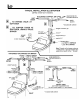
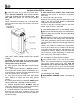
INSTALLATION STEPS 1. INSTALL BYPASS VALVE: NOTE: be sure the turbine and support are firmly in place, in the valve outlet. Blow into the valve port and observe the turbine for free rotation. !" Push the bypass valve (lubricate o-ring seals) into both ports of the valve…Figures 1A and 1C. ! Snap the two large plastic clips in place, from the top, down...Figures 1A and 1B. Be sure they snap into place. Pull on the adaptors, or bypass valve, to make sure they held securely in place. 2.
! Put grounding clamps (see step 5) on copper tubes before soldering. ! When turning threaded pipe fittings onto plastic fittings, use care not to cross-thread. ! Use pipe joint compound on all external pipe threads. !Support inlet and outlet plumbing in some manner (use pipe hangers to keep the weight off the valve fittings. 5. INSTALL GROUNDING CLAMPS AND WIRE (IF NEEDED): ! To maintain electrical ground continuity in the house cold water piping, install the included ground clamps as shown in Figure 2.
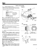
INSTALLATION STEPS, continued ! Locate the other end of the hose at the drain point. DO NOT ELEVATE THIS HOSE HIGHER THAT THE ELBOW ON THE BRINE TANK. DO NOT TEE THIS HOSE TO THE VALVE DRAIN HOSE. NOTE: This drain is for safety only. If the brine tank should over-fill with water, the excess is carried to the drain. 8.
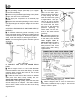
PROGRAMMING THE ELECTRONIC DEMAND TIMER MW-15 ! TIMER SETTINGS REQUIRED...upon installation, and after an extended power outage (see Program Memory, page 18). NOTES: " WHEN THE TRANSFORMER IS PLUGGED INTO THE ELECTRICAL OUTLET (STEP 11, PAGE 9), a flashing 12:00AM and PRESENT TIME show in the display area. Program the timer as instructed below. If - - - - is flashing, use the UP + button to set the code to SR14. If you pass by the correct code number, use the DOWN - button.
PROGRAMMING THE ELECTRONIC DEMAND TIMER, continued !" SET WATER HARDNESS NUMBER NOTE: If a flashing 25 (factory default) and the word HARDNESS do not show in the display, press SELECT until they do. 1. Press the UP or DOWN button to set your water hardness number in the display. DOWN moves the display down to 1. UP moves the display up to 95. NOTE: Each press of a button changes the display by 1 between 1 and 25. Above 25, the display changes 5 at a time; 25, 30, 35, etc.
SANITIZING PROCEDURES Care is taken at the factory to keep your water softener clean and sanitary. Materials used to make the softener will not infect or contaminate your water supply, and will not cause bacteria to form or grow. However, during shipping, storage, installing and operating, bacteria could get into the softener. For this reason, sanitizing as follows is suggested! when installing. 1. Be sure to complete all installation steps, including timer programming. 2. Pour about 3/4 oz of common 5.
WATER AND WATER CONDITIONING WATER . . . . . . . . . . . . . . . . . . . . . . . . . . . . . . . . . . . . . . . . . . . . . . . . . . . . . . . . . . . . . . . . . . . . Municipal water supplies come from surface reserMan's very existence depends on water. It is one of voirs, such as lakes and rivers, or from underground the basic commodities of life. Water is best as nature reservoirs. Usually, municipalities chlorinate the provides it, is a common misconception.
WATER AND WATER CONDITIONING, continued $ Colloidal and inorganically bound iron is of ferric or ferrous form that will not filter or exchange out of water. In some instances, treatment may improve colloidal iron water, but always CONSULT A QUALIFIED WATER CHEMISTRY LAB before attempting to treat it. Colloidal iron water usually has a yellow appearance when drawn. After standing for several hours, the color persists and the iron does not settle, but remains suspended in the water.
WATER FLOW THROUGH SOFTENER 15
GENERAL WATER SOFTENER MAINTENANCE CHECKING THE SALT STORAGE LEVEL, AND REFILLING . . . . . . . . . . . . . . . . . . . . . . . . . . . . . . . . . Use clean water softener salt only, at least 99.5% Brine (salt dissolved in water) is needed for each pure. NUGGET, PELLET or coarse SOLAR salts are and every regeneration. The water for making brine recommended. Do not use rock, block, granulated, is metered into the salt storage area by the softener and ice cream making salts.
GENERAL WATER SOFTENER MAINTENANCE, continued CLEANING THE NOZZLE AND VENTURI ASSEMBLY . . . . . . . . . . . . . . . . . . . . . . . . . . . . . . . A clean nozzle and venturi is needed for the softener to work right. This small unit makes the suction to move brine from the salt storage area to the resin tank during regeneration. If it becomes plugged with sand, silt, dirt, etc., the softener will not work and you will get hard water. To get to the nozzle and venturi, remove the softener top cover.
ELECTRONIC DEMAND TIMER FEATURES, AND SERVICE NOTE: SEE PAGE 10 TO SET THE TIMER TO THE CORRECT TIME OF DAY, WATER HARDNESS NUMBER, AND RECHARGE START TIME. NORMAL OPERATION, TIMER DISPLAYS . . . . . . . . . . . . . . . . . . . . . . . . . . . . . . . . . . . . . . . . . . . During normal operation, the present time of day, and AM or PM, show in the time display area. feature: OPTIONAL RECHARGE CONTROLS . . . . . . . . . . . . . . . . . . . . . . . . . . . . . . . . . . . . . . . . . . . .
ELECTRONIC DEMAND TIMER FEATURES, AND SERVICE, continued California Efficiency Requirement Your water softener has a "High Efficiency" feature with an "ON" or "OFF" setting. This softener setting is shipped in the "OFF" position, which utilizes the maximum rated capacity while most often achieving maximum salt efficiencies.
ELECTRONIC DEMAND TIMER FEATURES, AND SERVICE, continued service: MANUAL INITIATED ELECTRONICS DIAGNOSTIC . . . . . . . . . . . . . . . . . . . . . . . . . . 1. To enter diagnostics, press and hold the SELECT button until (000 - -) shows in the display. (A)The first 3 digits indicate water meter operation as follows: #000 (steady) = soft water not in use…no flow through the meter. - OPEN A NEARBY SOFT WATER FAUCET #000 to 199 (continual) = repeats display for each gallon of water passing through the meter.
ELECTRONIC DEMAND TIMER FEATURES, AND SERVICE, continued service: MANUAL ADVANCE REGENERATION CHECK……………………………………………… This check verifies proper operation of the valve motor, brine tank fill, brine draw, regeneration flow rates, and other controller functions. First, make the initial checks, and the manual initiated diagnostics. NOTE: The face plate display must show a steady time (not flashing). 1. Press the RECHARGE button and hold in for 3 seconds.
WATER FLOW THROUGH VALVE 22
WATER FLOW THROUGH VALVE 23
REPAIR PARTS 24
REPAIR PARTS NOTES: 25
REPAIR PARTS 26
REPAIR PARTS 27
If you have a defective part or assembly under warranty, please fill in a parts return tag. Cut out the tag and include it with the defective part when you return it to the place where you purchased the softener. To avoid destroying the repair parts information on the reverse side of this page, make a photocopy of the return tags to use.