EcoSmart™ Troubleshooting Guide Models POU 3.5 & 6 kW This guide is designed for installers or homeowners to help troubleshoot any issues experienced during the lifetime of the tankless water heater. For additional help, go to ecosmartus.com/support/videos and view the troubleshooting videos, or email technical support at support@ecosmartus.com. | © 2018 All rights reserved. | EcoSmart™ | www.ecosmartus.
This page will help you navigate our troubleshooting guide. Read the each step carefully and do not skip ahead. For additional help, contact technical support by email at support@ecosmartus.com, or call 877474-6473, Monday-Friday, 9:00 am—5:00 pm EST.
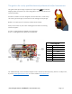
This guide is for use by qualified electrical professional and/or homeowners. This guide takes you through a sequence of steps that MUST be followed. Skipping steps will prevent you from being able to successfully detect and resolve a problem. All electric tankless units are designed to be checked with a multi-clamp volt meter (pictured right) to measure for both voltage and amperage. Below is an inside view of an electric tankless water heater.
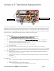
Activity A | Thermistors Replacement Thermistor Connection Outlet thermistor Each heater is equipped with 1 outlet thermistor (see image above). It is located on the hot water side (Left side of the unit) red wire. The function of the thermistors is to measure the outgoing water temperature and display it on the LED located on the front of the unit.
c. Issues not resolved i. Please go to Activity C | Electrical Connection | © 2018 All rights reserved. | EcoSmart™ | www.ecosmartus.
Activity B | Flow Meter Troubleshooting Flow meter The flow meter is located on the inlet side of the water heater and has 4 Phillips head screws and a small black wire (see image above). The flow meter is equipped with a small propeller that must spin freely counter clockwise in order to activate heater. The flow meter controls the activation of the water heater by sensing water flow.
c. If the LED display is illuminated with water flowing, you can begin to slow down the GPMs. Close all running water taps except for 1 sink to verify water is heating and LED display is staying on. Leave this sink running for approximately 45-60 seconds, during this time the unit should be heating water. i. If the LED display is not staying illuminated, continue to Step 3. 3. Thoroughly clean the flow meter. This process takes 10 to 15 minutes. a. Turn OFF breaker i.
Activity C | Electrical Connection Models 8-13 kW are supplied with a 2-prong terminal block (part number 6, on page 3). Each one of the connection sets must be connected to an independent double pole breaker. 8 kW requires 1 double pole 40 amp breaker 11-13 kW requires 1 double pole 60 amp breaker Check that the set of wires from each leg are connected correctly, otherwise the unit will not function as designed. To make sure wiring is connected correctly, perform the following test. 1.
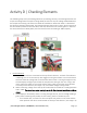
Activity D | Checking Elements The following steps verify the heating elements are working correctly. The heating elements will only draw voltage when hot water is being called for and uses only the voltage needed based on the temperature setting. This feature is called self-modulation. When hot water is ‘demanded’ the elements instantly draw power. The heating elements then work in series, which means that the element #1 (located on the inlet side of the unit) will be the first to draw power.
ii. If the reading is in the range of 6-10 ohms, the element is good and it will be necessary to contact technical support team for further troubleshooting. iii. If the ohm reading is lower than 5 or higher than 10, the element will need to be replaced. Element failures are commonly due to air pockets, scale/sediment buildup, and/or freeze damage. D. If the heater is still within warranty, part will be covered. If not, parts can be purchased online or through our support team. i.
Activity E | Required Maintenance When scale forms on elements, it is due to minerals such as calcium and magnesium found in water. There are three ways to deal with this this issue. Manual Maintenance, Recirculating Maintenance, and Filtration Maintenance. Please Note: It is the responsibility of the unit owner to be aware of your water quality and its effect on the heater.
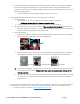
5. Remove element a. The element has a brass hexagon manifold located on top. Grip hexagon brass top of heating element and rotate counter clockwise to unscrew from the copper tank, see picture below; Cleaning Process a. Place elements in a small bucket and add white vinegar. Cover element to just under hexagon brass top. Do not submerge whole element. Vinegar can also be poured into heating chamber if needed. We recommend letting elements soak for at least 3 hours. Replacing Elements a.
11. Operate the pump and allow vinegar to circulate through the water heater for at least 3 hours at a rate of 4 gallons per minute. Rinse Vinegar from Water Heater 1. Remove free end of drain hose from bucket and put in a sink or outside to drain 2. Allow vinegar to completely drain from drain hose 3. Disconnect pump outlet hose from service valve on the cold water line. Use bucket to capture any excess water that may be in the line. 4. Screw cap tightly back onto service valve of cold water line* 5.
| © 2018 All rights reserved. | EcoSmart™ | www.ecosmartus.
Activity F | Sizing Meeting temperature rise (ability to heat water to set/desired output temperature) for an electric tankless water heater is dependent on the climate/region where a heater is installed. Colder incoming water requires a larger kilowatt model. The same applies for flow rate. To meet the demand for higher flow rates, a higher kilowatt model is needed. There are 3 pieces of information needed to determine what size electric tankless water heater is right for you.