OWNER’S MANUAL How to maintain and operate your EcoWater electronic demand water system R MODELS ESD 2502R30 ESD 2502R39 MODEL ESD 518 Systems Tested and Certified by NSF International and WQA against NSF/ANSI Standard 44 for softener performance. EcoWater Systems PO Box 64420, St. Paul MN 55164--- 0420 Part No. 7277268 (Rev.
GUARANTEE BOND LIMITED WARRANTY EcoWater Systems LLC Advantage Warranty Series ESD 518, ESD 2502R30 & ESD 2502R39 Water Systems Congratulations! You have just purchased the highest quality water conditioning product on the market. To register your warranty, complete the enclosed Warranty Registration Card and mail it within 30 days of purchase.
SAFETY GUIDES Follow the installation instructions carefully. Failure to install the EcoWater softener properly voids the warranty. Before you begin installation, read this entire manual. Then, obtain all the materials and tools you will need to make the installation. Check local plumbing and electrical codes. The installation must conform to them. In Massachusetts, plumbing codes of Massachusetts shall be adhered to. Consult with your licensed plumber.
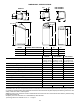
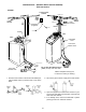
DIMENSIONS / SPECIFICATIONS ESD 518 OUT A ESD 2502R30 ESD 2502R39 IN 20” IN 14” A 16” 14” OUT 14” IN --- OUT 16” IN --- OUT C C B 36--- 9/16” 32” B 32--- 1/2” MODEL NOMINAL RESIN TANK SIZE A B C ESD 518 8” DIA. X 35” 3--- 3/8” 38--- 1/8” 45” ESD 2502R30 8” DIA. X 40” 3--- 3/8” 41.6” 48.75” ESD 2502R39 10” DIA. X 47” 3--- 3/4” 49.8” 56.6” Rated Capacity (grains @ salt dose) Service Flow Rate (gpm) ESD 518 ESD 2502R30 ESD 2502R39 10,100 @ 2.0 lbs 21,500 @ 6.
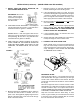
INSTALLATION -- (MODELS ESD 518 & ESD 2502R30) (ESD 518 shown) FIGURE 1 CONDITIONED WATER bypass valve 120V, 60Hz outlet HARD WATER HARD WATER 3--- valve bypass system outlet valve transformer (supplied) to timer OUTLET OUTLET inlet valve to timer INLET INLET valve drain hose brine tank overflow hose 1---1/2” airgap valve drain hose 1---1/2” airgap brine tank overflow hose Tie or wire valve drain hose in place, to keep over floor drain.
INSTALLATION (continued) -- (MODELS ESD 518 & ESD 2502R30) 5. INSTALL INLET AND OUTLET ADAPTORS, OR THE OPTIONAL BYPASS VALVE. 7. Referring to page 5, run inlet and outlet pipes to the softener, observing all of the following notes. H If the optional bypass valve is not used, be sure to use a three valve bypass as typically shown in Figure 1. Position in “bypass” only if needed for softener repairs. The bypass valve maintains continuity of the water supply when the softener is disconnected.
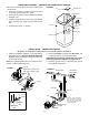
BRINE TANK ASSEMBLY -- (MODELS ESD 2502R30 & ESD 2502R39) Note: On some models, the factory may complete steps 1 and 2 below. 1. Locate the brinewell in position and secure with a screw and nut (from parts skin---pack). FIGURE 3 nut brinewell cover compression nut 2. Lower the brine valve into the brinewell and install the brinewell cover. brine tubing 3. Insert the grommet into the hole in the tank sidewall. Then, push the hose adaptor elbow into the grommet. brine tank 4. Continue with step 6.
INSTALLATION (continued) -- (MODEL ESD 2502R39) 4. Run the valve and brine tank overflow drain hoses (Figure 6). Secure the valve drain hose to the drain fitting with the included hose clamp. Provide a minimum 1---1/2” air gap at the floor drain, standpipe, laundry tub, or other approved drain. If you need to elevate the valve drain hose to get to the drain point, do not raise more than 8’ above the floor. The gravity overflow hose must be lower than the drain fitting along the entire run.
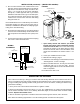
FIGURE 7 UP keypad display RECHARGE keypad DOWN keypad SELECT keypad When the transformer is plugged in, a model code shows in the face plate display for the first few seconds. The model code for your water softener is S518, S30 OR H40, as shown in the following drawing. The model code is followed by a test number (example: J1.0). After the test number, 12:00 PM begins to flash. The words PRESENT TIME show in the display. If the present time is between noon and midnight, be sure PM shows.
3. SET RECHARGE (REGENERATION) TIME: NOTE: California regulations require the efficiency setting to be ON for sale in California. Press the SELECT keypad once to display 2:00 AM (flashing) and RECHARGE TIME. At the 2:00 AM RECHARGE TIME setting, the softener begins regeneration at 2:00 AM, ending no later than 4:00 AM. This is a good time in most households because water is not being used. NOTE: When efficiency setting is set to on, an icon will show in the upper right hand corner of the display.
EXTRA RECHARGE play is flashing. The HARDNESS and RECHARGE TIME never require resetting unless a change is desired. Even if the timer is incorrect after a long power outage, the softener works as it should to keep your water soft. However, regenerations may occur at the wrong time of day until you reset the timer to the correct time of day. Sometimes, a manually started regeneration (recharge) may be desired, or needed. Two examples are: .
REFILLING WITH SALT CLEANING THE NOZZLE AND VENTURI A clean nozzle and venturi (Figure 8) is a must for the EcoWater System Unit to work right. This small unit creates the suction to move brine from the brine tank, into the resin tank. If it should become plugged with sand, silt, dirt, etc., the EcoWater System Unit will not work, and you will get hard water. To get to the nozzle and venturi, remove the EcoWater System Unit top cover.
RESIN BED CLEANING FIGURE 9 plug distributor tube while adding resin If the water supply contains ‘‘clear water ’’ iron (see page 9), regular resin bed cleaning is needed to keep the bed from coating with iron. Use resin bed cleaner, available from EcoWater, following directions on the container. Clean the resin every 6 months, or more often if iron appears in your conditioned water supply.
REPAIR PARTS -- ALL MODELS Valve Assembly (see pages 16 --- 19 ) 1 2 38 39 40 19 20 21 22 25 23 3 6 24 37 4 36 26 29 5 35 27 7 30 34 8 33 28 31 32 41 2 9 10 5 11 12 10 9 13 12 8 13 14 16 14 15 16 17 11 18 15 17 14
REPAIR PARTS -- ALL MODELS KEY NO. PART NO. KEY NO. PART NO. 1 7252373 2 7218662 Transformer, 24V--- 10VA 23 7105047 Repl. Distributor (bottom) Top Cover (ESD 518) 24 7176292 Clamp Section, 2 req. 7218670 Top Cover (ESD 2502 models) 25 7088033 Clamp Retainer, 2 req. 26 7114787 Resin Tank, 8” dia. x 35”, ESD 518 7113058 Resin Tank, 8” dia. x 40”, ESD 2502R30 7092202 Resin Tank, 10” dia. x 47”, ESD 2502R39 0502272 Resin, 1 cu ft (stand.
REPAIR PARTS -- ESD 518 & ESD 2502R30 1 2 50 49 3 48 4 47 51 5 6 7 52 8 46 42 41 11 12 45 40 10 9 18 17 13 39 14 44 15 38 19 16 37 20 36 22 43 35 21 23 wear--- strip 24 25 31 seal cross--- section view 26 34 27 33 28 30 32 29 16
REPAIR PARTS -- ESD 518 & ESD 2502R30 KEY NO. PART NO. 1 7224087 KEY NO. PART NO. Screw, #8-32 x 1” (2 req.) 31 7081201 Retainer (Nozzle & Venturi) 7170319 O-Ring, 1/4 x 3/8 (2 req.) DESCRIPTION DESCRIPTION 2 7228544 Motor (incl. 2 ea. of Key No. 1) 32 3 0900857 Screw, #6-20 x 3/8 (2 req.) 33 7081104 Nozzle & Venturi Housing 4 7231385 Motor Plate 34 1202600 Nut - Ferrule 5 0503288 Bearing 35 7095030 Cone Screen 6 7113927 Cam and Gear 36 1148800 Flow Plug, .
REPAIR PARTS -- ESD 2502 R39 1 2 46 3 45 4 44 5 6 47 7 8 43 48 41 11 42 40 13 seal 38 9 12 wear--- strip 39 10 14 cross--- section view 15 37 26 16 36 21 17 35 34 18 19 20 27 28 22 33 23 32 24 29 31 25 30 18
REPAIR PARTS -- ESD 2502 R39 KEY NO. PART NO. 1 7224087 2 7228544 3 KEY NO. PART NO. Screw, #8-32 x 1” (2 req.) 27 0900060 O-ring Motor (incl. 2 ea. of Key No. 1) 28 7081201 Retainer (Nozzle & Venturi) 7231393 Motor Plate 29 7195482 Seal (Nozzle & Venturi) 4 0900857 Screw, #6-20 x 3/8 (3 req.) 30 7171145 Valve Body 5 7171250 Bearing 31 7170319 O-ring, 1/4 x 3/8 (2 req.