
Owner`s manual


6
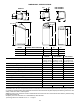
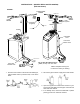
INSTALLATION (continued) -- (MODELS ESD 518 & ESD 2502R30)
5. INSTALL INLET AND OUTLET ADAPTORS, OR
THE OPTIONAL BYPASS VALVE.
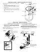
IMPORTANT: Be sure the
turbine, turbine support
and sensor housing are
firmly in position, in or on
the valve outlet.
H INLET AND OUTLET ADAPTORS --- Push adaptors
into the valve ports. Be sure the o---ring seals a re lu-
bricated with silicone grease or Vaseline.
-- OR --
BYPASS VALVE --- Push the bypass valve into the
valve ports (can be inverted for connecting to floor
level plumbing). B e sure t he o---ring seals are lubri-
cated with silicone grease or Vaseline.
H SNAPTHETWOLARGEHOLDINGCLIPSINTO
PLACE, FROM THE TOP DOWN AS SHOWN. BE
SURE THEY SNAP FIRMLY INTO PLACE, SO THE
ADAPTORS, OR BYPASS VALVE , DO NOT PULL
OUT.
FIGURE 2
6. Move the softener into installation position, setting on
a s mooth and level surface. If needed, set it on a
piece of 3/4” thick plywood (slightly larger than the
bottom of the brine tank). Then shim under the ply-
wood to level the softener.
7. Referring to page 5, run inlet and outlet pipes to the
softener, observing all of the following notes.
H If the optional bypass valve is not used, be sure to
use a three valve bypass as typically shown in Figure
1. Position in “bypass” only if needed for softener re-
pairs. The bypass valve maintains continuity of the
water supply w hen the softener is disconnected.
H Be sure to plumb so HARD WATER
flows TO the soft-
ener valve INLET
.
H If sw eat soldering, first disconnect copper pipes from
plastic softener parts. DO NOT SOLDER WITH
COPPER CONNECTED TO THE SOFTENER OR
PLASTIC PARTS WILL BE DAMAGED.
H If using t hreaded fittings, use extreme care not to
cross thread onto plastic.
H Support inlet and outlet plumbing in some manner,
to keep the weight off of the softener valve.
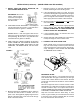
8. CONNECT THE VALVE DRAIN HOSE
Attach a length of 3/8” I.D. hose to the valve drain fit-
ting. Use a hose clamp to hold it in place. Place the
other end of the hose over a floor drain, laundry tub,
sump, standpipe or other suitable drain. BE SURE
TO OBSERVE L OCAL CODES.
drain fitting
hose clamp
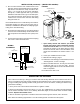
IMPORTANT NOTES:
Leave an air gap of about 1---1/2” between the end of the
hose and the drain. This gap is needed so you don’t get
a back ---flow of sewer water into the softener. DO NOT
put the end of the hose into the drain or connect without
the a ir gap.
Place and support the hose so it does not kink or have
sharp bends. Tie or wire the hose in place so water pres-
sure will not make it “whip”. Do not pinch the hose shut.
THE SOFTENER WILL NOT WORK IF THIS DRAIN HOSE
IS PINCHED, PLUGGED OR CLOSED IN ANY WAY.
Keep the hose lower than the drain fitting. In some
homes, to get to a drain you must raise the hose and run
it over head. If you need an overhead drain, do not raise
thehosemorethan8’abovethefloor.