
Owner`s manual
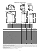
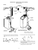
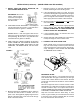


FIGURE 4
FIGURE 5
Bypass Valve
Inlet Val ve
Outlet Valve
Valve Inlet
soft water
hard water
hard water to
outside faucets
OUTLET
bypass
valve
clip (2)
clip (2)
INLET
copper tubes (install in soft-
ener valve or bypass valve)
Soldered copper, thr eaded, or
PVC plastic pipe and fittings.
Plumb to copper tubes. Elimi-
nate 3 valves shown above if us-
ing optional bypass.
o--ring seal
copper tube
clip
IN
OUT
from valve
outlet
GROUND CONTINUITY
to valve
inlet
ground
clamp
7
BRINE TANK ASSEMBLY -- (MODELS ESD 2502R30 & ESD 2502R39)
Note: On some models, the factory may complete steps
1and2below.
1. Locate the brinewell in position and secure with a
screw and nut (from parts skin---pack).
2. Lower the brine valve into the brinewell and install the
brinewell cover.
3. Insert the grommet into the hole in the t ank sidewall.
Then, push the hose adaptor elbow into the grom-
met.
4. Continue w ith step 6., on page 8.
screw
brine valve
brinewell
brine tank
brine tubing
elbow
grommet
nut
FIGURE 3
brinewell cover
compression nut
INSTALLATION -- (MODEL ESD 2502R39)
BE SURE TO READ AND COMPLY WITH ALL GUIDES LISTED ON PAGE 3.
1. Install the installation adaptors, or the optional by-
pass valve (Figure 4). Be sure clips hold parts firmly
in place. Pull on the adaptors or bypass valve to in-
sure they are secure.
Note: If the optional bypass valve is not used, be sure to
install a 3---valve bypass (Figure 5).
2. Run the hard water supply to the valve inlet,and
conditioned water out from the valve outlet.
CAUTION: Do all soldering, and allow to cool, before
connecting pipe to the adaptors or bypass valve.
3. Install the ground clamp if cold water pipe ground
continuity was interrupted.