Preface Copyright This publication, including all photographs, illustrations and software, is protected under international copyright laws, with all rights reserved. Neither this manual, nor any of the material contained herein, may be reproduced without written consent of the author. Version 2.0A Disclaimer The information in this document is subject to change without notice.
ii Declaration of Conformity This device complies with part 15 of the FCC rules. Operation is subject to the following conditions: • • This device may not cause harmful interference, and This device must accept any interference received, including interference that may cause undesired operation. Canadian Department of Communications This class B digital apparatus meets all requirements of the Canadian Interferencecausing Equipment Regulations.
iii TABLE OF CONTENTS Preface i Chapter 1 1 Introducing the Motherboard 1 Introduction............................................................................................1 Features...................................................................................................2 Motherboard Components...................................................................4 Chapter 2 7 Installing the Motherboard 7 Safety Precautions.................................................................
iv Integrated Peripherals..................................................................32 Power Management Setup.............................................................33 PCI/PnP Configurations...............................................................35 PC Health Status...........................................................................36 Frequency/Voltage Control............................................................38 Load Default Settings........................................
1 Chapter 1 Introducing the Motherboard Introduction Thank you for choosing this motherboard. This motherboard is a high performance, enhanced function motherboard that supports AMD Phenom TM processor (socket AM2+)/AMD AthlonTM 64 X2 Dual-Core/AthlonTM 64/Sempron™ processors for high-end business or personal desktop markets. The motherboard incorporates the AMD 740G (RS740) Northbridge (NB) and SB700 Southbridge (SB) chipsets. The Northbridge supports the HyperTransportTM 1.0 interface.
2 Feature Processor This motherboard uses a Socket AM2+ that carries the following features: • Accommodates AMD PhenomTM processor (socket AM2+) AMD AthlonTM 64 X2 Dual-Core/AthlonTM 64/Sempron™ processors • Supports HyperTransportTM (HT) 1.0 interface speeds HyperTransportTM Technology is a point-to-point link between two devices, it enables integrated circuits to exchange information at much higher speeds than currently available interconnect technologies. This board supports CPU up to 95W TDP only.
3 Onboard LAN (Optional) The onboard LAN provides the following features: • • • Integrated 10/100/1000 Base-T Transceiver Integrated 10/100/1000 Mbps IEEE 802.3 compliant IEEE 802.3u Auto-Negotiation • • • Integrated 10BASE-T/100BASE-TX Transceiver Integrated IEEE802.3z compliant IEEE 802.3u Auto-Negotiation Expansion Options The motherboard comes with the following expansion options: • One PCI Express x16 for Graphics Interface • One PCI Express x1 slot • Two 32-bit PCI v2.
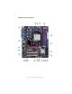
4 Motherboard Components Introducing the Motherboard
5 Table of Motherboard Components LABEL 1. CPU Socket 2. CPU_FAN 3. SYS_FAN 4. DDR2_1~2 5. ATX_POWER 6. IDE1 7. SATA1~6 8. CLR_CMOS 9. F_PANEL 10. SPK 11. LPT 12. USBPWR_F2 13. USBPWR_F1 14. F_USB1~3 15. IR 16. SPDIFO 17. CD_IN 18. F_AUDIO 19. PCI1~2 20. PCIEX 21. PCIEX16 22. USBPWR_R1 23.
6 Memo Introducing the Motherboard
7 Chapter 2 Installing the Motherboard Safety Precautions • • • • • Follow these safety precautions when installing the motherboard Wear a grounding strap attached to a grounded device to avoid damage from static electricity Discharge static electricity by touching the metal case of a safely grounded object before working on the motherboard Leave components in the static-proof bags they came in Hold all circuit boards by the edges.
8 Do not over-tighten the screws as this can stress the motherboard. Checking Jumper Settings This section explains how to set jumpers for correct configuration of the motherboard. Setting Jumpers Use the motherboard jumpers to set system configuration options. Jumpers with more than one pin are numbered. When setting the jumpers, ensure that the jumper caps are placed on the correct pins. The illustrations show a 2-pin jumper. When the jumper cap is placed on both pins, the jumper is SHORT.
9 Checking Jumper Settings The following illustration shows the location of the motherboard jumpers. Pin 1 is labeled. Jumper Settings Jumper Type Description Setting (default) 1-2: NORMAL CLR_CMOS 3-pin Clear CMOS 2-3: CLEAR CMOS Before clearing the CMOS, make sure to turn off the system.
10 Connecting Case Components After you have installed the motherboard into a case, you can begin connecting the motherboard components. Refer to the following: 1 2 3 4 5 6 Connect the CPU cooling fan cable to CPU_FAN. Connect the standard power supply connector to ATX_POWER. Connect the case speaker cable to SPK. Connect the case switches and indicator LEDs to the F_PANEL. Connect the system cooling fan connector to SYS_FAN. Connect the auxiliary case power supply connector to ATX12V.
11 CPU_FAN: Cooling FAN Power Connector Pin 1 2 3 4 Function Signal Name GND +12V System Ground Power +12V Sense Sensor PWM CPU FAN control Users please note that the fan connector supports the CPU cooling fan of 1.1A~2.2A (26.4W max.) at +12V. ATX_POWER: ATX 24-pin Power Connector Pin 1 2 3 4 5 6 7 8 9 Signal Name +3.3V Ground +5V Ground +5V Ground PWRGD +5VSB 10 11 +12V 12 Pin Signal Name 13 14 15 16 17 18 19 20 21 +3.3V +3.3V -12V COM PS_ON COM COM COM -5V +5V +5V +12V 22 23 +3.
12 Front Panel Header The front panel header (F_PANEL) provides a standard set of switch and LED headers commonly found on ATX or Micro ATX cases.
13 Installing Hardware Installing the Processor Caution: When installing a CPU heatsink and cooling fan make sure that you DO NOT scratch the motherboard or any of the surfacemount resistors with the clip of the cooling fan. If the clip of the cooling fan scrapes across the motherboard, you may cause serious damage to the motherboard or its components. On most motherboards, there are small surface-mount resistors near the processor socket, which may be damaged if the cooling fan is carelessly installed.
14 CPU Installation Procedure The following illustration shows CPU installation components. 1 2 3 4 5 Install your CPU. Pull up the lever away from the socket and lift up to 90-degree angle. Locate the CPU cut edge (the corner with the pin hold noticeably missing). Align and insert the CPU correctly. Press the lever down and apply thermal grease on top of the CPU. Put the CPU Fan down on the retention module and snap the four retention legs of the cooling fan into place.
15 Installing Memory Modules This motherboard accommodates two memory modules. It can support two 240-pin DDR2 800/667/533/400. The total memory capacity is 16 GB. DDR2 SDRAM memory module table Memory module Memory Bus DDR2 400 200 MHz DDR2 533 DDR2 667 DDR2 800 266 MHz 333 MHz 400 MHz You must install at least one module in any of the two slots. Each module can be installed with 8 GB of memory.
16 Table A: DDR2 (memory module) QVL (Qualified Vendor List) The following DDR2 800/667/533/400 memory modules have been tested and qualified for use with this motherboard. Type Size Vendor Module Name DDR2 400 256 MB Hynix HYMP532U646-E3 AA 512 MB Nanya NT512T64U88A0F-5A 256MB Elixir M2U25664TUH4A0F-37B DDR2 533 512MB Aeneon AET660UD00-370A98Z Infineon HYS64T64400HU-3.7-A Kingston KVR533D2N4/512 PQI MEABR321LA01AA Samsung M378T6553BGO-CD5 1GB Infineon HYS64T128920HU-3.
17 Type Size Vendor Module Name 256MB Infineon HYS64T32000HU-25F-B A-DATA M2OAD6G3H3160I1E53 Aeneon AET660UD00-25DB98X Apacer AU512E800C5KBGC 512MB DDR2 800 1GB APOGEE AU51082-800P505 Infineon HYS64T64000HU-25F-B Kingston KHX6400D2ULK2/1G Nanya NT512T64U88BOBY-25C PSC AL6E8E63H-8E1 APOGEE AU1G082-800P000 Infineon HYS64T128020HU-25F-8 Kingston KHX6400D2ULK2/2G Nanya NT1GT64U8HBOBY-25C PSC AL7E8E63H-8E1 UMAX 53016042-7100B Installing a Hard Disk Drive/CD-ROM/SATA Hard Dri
18 IDE devices enclose jumpers or switches used to set the IDE device as MASTER or SLAVE. Refer to the IDE device user’s manual. Installing two IDE devices on one cable, ensure that one device is set to MASTER and the other device is set to SLAVE. The documentation of your IDE device explains how to do this. About SATA Connectors Your motherboard features six SATA connectors supporting a total of six drives.
19 Installing Add-on Cards The slots on this motherboard are designed to hold expansion cards and connect them to the system bus. Expansion slots are a means of adding or enhancing the motherboard’s features and capabilities. With these efficient facilities, you can increase the motherboard’s capabilities by adding hardware that performs tasks that are not part of the basic system.
20 Follow these instructions to install an add-on card: 1 2 3 Remove a blanking plate from the system case corresponding to the slot you are going to use. Install the edge connector of the add-on card into the expansion slot. Ensure that the edge connector is correctly seated in the slot. Secure the metal bracket of the card to the system case with a screw.
21 Connecting Optional Devices Refer to the following for information on connecting the motherboard’s optional devices: F_USB1~3: Front Panel USB headers The motherboard has four USB ports installed on the rear edge I/O port array. Additionally, some computer cases have USB ports at the front of the case. If you have this kind of case, use auxiliary USB connector to connect the front-mounted ports to the motherboard.
22 LPT: Onboard parallel port header This is a header that can ba used to connect to the printer, scanner or other devices.
23 CD_IN: Analog audio input connector Pin 1 2 3 4 Signal Name Function CD_L Left CD-in signal GND Ground GND Ground CD_R Right CD-in signal SPDIFO: SPDIF out header This is an optional header that provides an S/PDIF (Sony/Philips Digital Interface) output to digital multimedia device through optical fiber or coaxial connector.
24 Connecting I/O Devices The backplane of the motherboard has the following I/O ports: PS2 Mouse Use the upper PS/2 port to connect a PS/2 pointing device. PS2 Keyboard Use the lower PS/2 port to connect a PS/2 keyboard. Serial Port (COM1) Use the COM port to connect serial devices such as mice or fax/modems. VGA Port Connect your monitor to the VGA port. DVI Port (optional) Use the DVI port to connect the monitor.
25 Chapter 3 Using BIOS About the Setup Utility The computer uses the latest “American Megatrends Inc. ” BIOS with support for Windows Plug and Play. The CMOS chip on the motherboard contains the ROM setup instructions for configuring the motherboard BIOS. The BIOS (Basic Input and Output System) Setup Utility displays the system’s configuration status and provides you with options to set system parameters.
26 Press DEL to enter SETUP Press the delete key to access the BIOS Setup Utility. CMOS Setup Utility -- Copyright (C) 1985-2007, American Megatrends, Inc.
27 Updating the BIOS You can download and install updated BIOS for this motherboard from the manufacturer’s Web site. New BIOS provides support for new peripherals, improvements in performance, or fixes for known bugs. Install new BIOS as follows: 1 If your motherboard has a BIOS protection jumper, change the setting to allow BIOS flashing. 2 If your motherboard has an item called Firmware Write Protect in Advanced BIOS features, disable it. (Firmware Write Protect prevents BIOS from being overwritten.
28 Standard CMOS Setup This option displays basic information about your system. CMOS Setup Utility -- Copyright (C) 1985-2007, American Megatrends, Inc. Standard CMOS Setup Date Time f f f f f f f f Fri 12/07/2007 00:11:10 SATA1 SATA 2 SATA 3 SATA4 SATA5 SATA6 IDE Master IDE Slave Not Detected Not Detected Not Detected Not Detected Not Detected Not Detected Not Detected Not Detected IDE BusMaster Help Item User [Enter], [TAB] or [SHIFT-TAB] to select a field. Use [+] or [-] to configure system Date.
29 Block (Multi-Sector Transfer) (Auto) If the feature is enabled, it will enhance hard disk performance by reading or writing more data during each transfer. PIO Mode (Auto) Use this item to set the PIO mode to enhance hard disk performance by optimizing the hard disk timing. DMA Mode (Auto) DMA capability allows user to improve the transfer-speed and data-integrity for compatible IDE devices. S.M.A.R.T. (Auto) The S.M.A.R.T.
30 Advanced Setup This page sets up more advanced information about your system. Handle this page with caution. Any changes can affect the operation of your computer. CMOS Setup Utility - Copyright (C) 1985-2007, American Megatrends, Inc. Advanced Setup HT Frequency AMD C&Q Quick Power on Self Test Boot Up Numlock Status APIC Mode 1st Boot Device 2nd Boot Device 3rd Boot Device Boot Other Device Auto Enabled Enabled On Enabled Hard Drive CD/DVD Removable Dev.
31 Boot Other Device (Yes) When enabled, the system searches all other possible locations for an operating system if it fails to find one in the devices specified under the First, Second and Third boot devices. Press to return to the main menu setting page. Advanced Chipset Setup This page sets up more advanced information about your system. Handle this page with caution. Any changes can affect the operation of your computer. CMOS Setup Utility - Copyright (C) 1985-2007, American Megatrends, Inc.
32 Integrated Peripherals This page sets up some parameters for peripheral devices connected to the system. CMOS Setup Utility - Copyright (C) 1985-2007, American Megatrends, Inc.
33 Parallel Port Mode (ECP) Use this item to select the parallel port mode. You can select Normal (Standard Parallel Port), ECP (Extended Capabilities Port), EPP (Enhanced Parallel Port), or BPP (Bi-Directional Parallel Port). ECP Mode DMA Channel (DMA3) Use this item to assign a DMA channel to the parallel port. Parallel Port IRQ (IRQ7) Use this item to assign IRQ to the parallel port. USB Functions (Enabled) Use this item to enable or disable the USB function.
34 Soft-off by PWR-BTTN (Instant off) Under ACPI (Advanced Configuration and Power management Interface) you can create a software power down. In a software power down, the system can be resumed by Wake Up Alarms. This item lets you install a software power down that is controlled by the power button on your system. If the item is set to Instant-Off, then the power button causes a software power down.
35 PCI / PnP Configuration This page sets up some parameters for devices installed on the PCI bus and those utilizing the system plug and play capability. CMOS Setup Utility - Copyright (C) 1985-2007, American Megatrends, Inc. PCI / PnP Setup Allocate IRQ to PCI VGA Init Display First Yes PCI mnlk: Move Enter : Select F1:General Help Help Item YES: Assigns IRQ to PCI VGA card if card requests IRQ. NO: Does not assign IRQ to PCI VGA card even if card requests an IRQ.
36 PC Health Status On motherboards support hardware monitoring, this item lets you monitor the parameters for critical voltages, temperatures and fan speeds. CMOS Setup Utility - Copyright (C) 1985-2007, American Megatrends, Inc. PC Health Status Help Item -=- System Hardware Monitor-=- fSmart Fan Function Press Enter Disabled Disabled : 64°C/147°F : 2616 RPM : 1.152V : 1.
37 DeltaT (+3) This item specifies the range that controls CPU temperature and keeps it from going so high or so low when smart fan works. SMART Fan Slope PWM value (5 PWM value/°C) This item is used to set the Slope Select PWM of the smart fan. Press to return to the PC Health Status page. Shutdown Temperature (Disabled) Enable you to set the maximum temperature the system can reach before powering down Warning Temperature (Disabled) This item enables or disables the warning temperature.
38 Frequency/Voltage Control This page enables you to set the clock speed and system bus for your system. The clock speed and system bus are determined by the kind of processor you have installed in your system. CMOS Setup Utility - Copyright (C) 1985-2007, American Megatrends, Inc. Frequency/Voltage Control Auto Detect DIMM/PCI CIK Memory Voltage Spread Spectrum CPU Over-clocking Function Help item Enabled 1.
39 Load Default Settings This option opens a dialog box to ask if you are sure to install optimized defaults or not. You select [OK], and then press , the Setup Utility loads all default values; or select [Cancel], and then press , the Setup Utility does not load default values. Supervisor Password This page helps you install or change a password. CMOS Setup Utility - Copyright (C) 1985-2007, American Megatrends, Inc.
40 User Password This page helps you install or change a password. CMOS Setup Utility - Copyright (C) 1985-2007, American Megatrends, Inc. User Password User Password : Not Installed Change User Password Help item Press Enter Install or Change the password. mnlk: Move Enter : Select +/-/: Value F10: Save ESC: Exit F1:General Help F9: Optimized Defaults User Password (Not Installed) This item indicates whether a user password has been set. If the password has been installed, Installed displays.
41 Chapter 4 Using the Motherboard Software About the Software CD-ROM The support software CD-ROM that is included in the motherboard package contains all the drivers and utility programs needed to properly run the bundled products. Below you can find a brief description of each software program, and the location for your motherboard version. More information on some programs is available in a README file, located in the same directory as the software.
42 Setup Tab Setup Click the Setup button to run the software installation program. Select from the menu which software you want to install. Browse CD The Browse CD button is the standard Windows command that allows you to open Windows Explorer and show the contents of the support CD. Before installing the software from Windows Explorer, look for a file named README.TXT, INSTALL.TXT or something similar. This file may contain important information to help you install the software correctly.
43 2. Click Next. The following screen appears: 3. Check the box next to the items you want to install. The default options are recommended. 4. Click Next run the Installation Wizard. An item installation screen appears: 5. Follow the instructions on the screen to install the items. 1. Drivers and software are automatically installed in sequence. Follow the onscreen instructions, confirm commands and allow the computer to restart a few times to complete the installation. 2.
44 Method 1. Run Reboot Setup Windows Vista will block startup programs by default when installing drivers after the system restart. You must select taskbar icon Run Blocked Program and run Reboot Setup to install the next driver, until you finish all drivers installation. Method 2. Disable UAC (User Account Control) * For administrator account only. Standard user account can only use Method 1.
45 2. Select Classic View. 3. Set User Account. 4. Select Turn User Account Control on or off and press Continue.
46 5. Disable User Account Control (UAC) to help protect your computer item and press OK, then press Restart Now. Then you can restart your computer and continue to install drivers without running blocked programs. Manual Installation Insert the CD in the CD-ROM drive and locate the PATH.DOC file in the root directory. This file contains the information needed to locate the drivers for your motherboard.