Preface Copyright This publication, including all photographs, illustrations and software, is protected under international copyright laws, with all rights reserved. Neither this manual, nor any of the material contained herein, may be reproduced without written consent of the author. Version 2.0A Disclaimer The information in this document is subject to change without notice.
ii Declaration of Conformity This device complies with part 15 of the FCC rules. Operation is subject to the following conditions: • • This device may not cause harmful interference. This device must accept any interference received, including interference that may cause undesired operation. Canadian Department of Communications This class B digital apparatus meets all requirements of the Canadian Interferencecausing Equipment Regulations.
iii TABLE OF CONTENTS Preface i Chapter 1 1 Introducing the Motherboard 1 Introduction............................................................................................1 Feature.....................................................................................................2 Motherboard Components...................................................................5 Chapter 2 7 Installing the Motherboard 7 Safety Precautions................................................................
iv Save & Exit Menu.........................................................................44 Updating the BIOS.......................................................................46 Chapter 4 47 Using the Motherboard Software 47 About the Software DVD-ROM/CD-ROM.......................................47 Auto-installing under Windows XP/Vista/7.....................................47 Running Setup...............................................................................48 Manual Installation.....
1 Chapter 1 Introducing the Motherboard Introduction Thank you for choosing the A75F-M2 motherboard. This motherboard is a high performance, enhanced function motherboard that supports socket for FM1 for AMD A series processor for high-end business or personal desktop markets. The motherboard is based on AMD A75 (Hudson D3) express chipset for best desktop platform.
2 Feature Processor This motherboard uses a socket FM1 that carries the following features: • Accommodates AMD A series processors • Supports CPU up to 100W TDP Chipset The AMD A75 (Hudson D3) chipset is based on an innovative and scalable architecture with proven reliability and performance. • • • • • • • • Supports one PCI-Express x16 Gen2 slot Supports two PCI Express x1 slots Compliant with PCI 2.3 specification at 33 MHz Supports six Serial ATA devices which speeds up to 6 Gb/s Integrated USB 3.
3 Expansion Options The motherboard comes with the following expansion options: • • • • One PCI Express x16 slots for Graphics Interface Two PCI Express x1 slots One 32-bit PCI v2.3 compliant slot Six 7-pin SATA connectors Integrated I/O • • • • • • • The motherboard has a full set of I/O ports and connectors: One PS/2 keyboard and mouse combo connector Six USB 2.0 ports One D-sub (VGA) port One HDMI port (DVI port optional) Two USB 3.
4 Specifications CPU • • FM1 for AMD A series processors Supports CPU up to 100W TDP Chipset • AMD A75 (Hudson D3) Memory • Dual-channel DDR3 memory architecture • 2 x 240-pin DDR3 DIMM sockets support up to 16 GB • Supports DDR3 DDR3 1866*1/1600/1333 SDRAM *1. Due to the limitation of chipset spec, it supports up to 1866 MHz for motherboard with a single DIMM per channel.
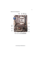
5 Motherboard Components Introducing the Motherboard
6 Table of Motherboard Components LABEL 1. CPU Socket 2. SYS_FAN 3. CPU_FAN 4. DDR3_1~2 5. ATX_POWER 6. SPI_DEBUG 7. SATA1~6 8. F_PANEL 9. SPDIFO 10. CLR_CMOS 11. F_USB1 12. F_USB2 13. USB3F 14. SPK 15. LPT 16. COM 17. CASE 18. PCI 19. PCIE1~2 20. PCIEX16 21. F_AUDIO 22. ATX12V COMPONENTS FM1 for AMD A series processors System cooling fan connector CPU cooling fan connector 240-pin DDR3 SDRAM slots Standard 24-pin ATX power connector SPI debug header-for factory use only Serial ATA 6.
7 Chapter 2 Installing the Motherboard Safety Precautions • • • • • Follow these safety precautions when installing the motherboard Wear a grounding strap attached to a grounded device to avoid damage from static electricity Discharge static electricity by touching the metal case of a safely grounded object before working on the motherboard Leave components in the static-proof bags they came in Hold all circuit boards by the edges.
8 Do not over-tighten the screws as this can stress the motherboard. Checking Jumper Settings This section explains how to set jumpers for correct configuration of the motherboard. Setting Jumpers Use the motherboard jumpers to set system configuration options. Jumpers with more than one pin are numbered. When setting the jumpers, ensure that the jumper caps are placed on the correct pins. The illustrations show a 2-pin jumper. When the jumper cap is placed on both pins, the jumper is SHORT.
9 Checking Jumper Settings The following illustration shows the location of the motherboard jumpers. Pin 1 is labeled. Name Type Description Setting (default) 1-2: NORMAL CLR_CMOS 3-pin Clear CMOS 1 2-3: CLEAR Before clearing the CLR_CMOS CMOS, make sure to turn off the system. To avoid the system unstability after clearing CMOS, we recommend users to enter the main BIOS setting page to “Load Default Settings” and then “Save Changes and Exit”.
10 Installing Hardware Installing the Processor Caution: When installing a CPU heatsink and cooling fan make sure that you DO NOT scratch the motherboard or any of the surface-mount resistors with the clip of the cooling fan. If the clip of the cooling fan scrapes across the motherboard, you may cause serious damage to the motherboard or its components. On most motherboards, there are small surface-mount resistors near the processor socket, which may be damaged if the cooling fan is carelessly installed.
11 CPU Installation Procedure The following illustration shows CPU installation components. 1 2 3 4 5 Install your CPU. Pull up the lever away from the socket and lift up to 90-degree angle. Locate the CPU cut edge (the corner with the pin hold noticeably missing). Align and insert the CPU correctly. Press the lever down and apply thermal grease on top of the CPU. Put the CPU Fan down on the retention module and snap the four retention legs of the cooling fan into place.
12 Installation Procedure Refer to the following to install the memory modules. 1 2 3 4 5 6 This motherboard supports unbuffered DDR3 SDRAM only. Push the latches on each side of the DIMM slot down. Align the memory module with the slot. The DIMM slots are keyed with notches and the DIMMs are keyed with cutouts so that they can only be installed correctly. Check that the cutouts on the DIMM module edge connector match the notches in the DIMM slot.
13 Expansion Slots Installing Add-on Cards The slots on this motherboard are designed to hold expansion cards and connect them to the system bus. Expansion slots are a means of adding or enhancing the motherboard’s features and capabilities. With these efficient facilities, you can increase the motherboard’s capabilities by adding hardware that performs tasks that are not part of the basic system.
14 Follow these instructions to install an add-on card: 1 2 3 Remove a blanking plate from the system case corresponding to the slot you are going to use. Install the edge connector of the add-on card into the expansion slot. Ensure that the edge connector is correctly seated in the slot. Secure the metal bracket of the card to the system case with a screw.
15 Connecting Optional Devices Refer to the following for information on connecting the motherboard’s optional devices: SATA1~6: Serial ATA connectors These connectors are used to support the new Serial ATAIII devices for the highest data transfer rates (6.0 Gb/s), simpler disk drive cabling and easier PC assembly. It doubles the transfer rate of current SATA 3.0Gb/s interface.
16 F_USB1~2: Front Panel USB 2.0 headers The motherboard has six USB 2.0 ports installed on the rear edge I/O port array. Additionally, some computer cases have USB 2.0 ports at the front of the case. If you have this kind of case, use auxiliary USB 2.0 connector to connect the frontmounted ports to the motherboard. Unlike F_USB2 in this mainboard, F_USB1 supports EZ Charger technology, provides 3 times current than general USB port in off mode for USB devices.
17 USB3F: Front Panel USB 3.0 header This Motherboard implements one USB 3.0 header supporting 2 extra front USB 3.0 ports, which delivers 5Gb/s transfer rate.
18 LPT: Onboard parallel port Header This is a header that can be used to connect to the printer, scanner or other devices.
19 Installing a SATA Hard Drive This section describes how to install a SATA hard drive. About SATA Connectors Your motherboard features six SATA connectors supporting a total of six drives. SATA refers to Serial ATA (Advanced Technology Attachment) is the standard interface for the IDE hard drives which are currently used in most PCs. These connectors are well designed and will only fit in one orientation.
20 Connecting I/O Devices The backplane of the motherboard has the following I/O ports: PS/2 mouse and keyboard combo connector Connect the PS/2 Keyboard or PS/2 Mouse to the PS/2 combo port. USB 2.0 Ports Use the USB 2.0 ports to connect USB 2.0 devices. USB 3.0 Ports Use the USB 3.0 ports to connect USB3.0 devices. LAN Port Connect an RJ-45 jack to the LAN port to connect your computer to the network. HDMI Port (DVI port optional) Connect the HDMI port to the HDMI devices.
21 Connecting Case Components After you have installed the motherboard into a case, you can begin connecting the motherboard components. Refer to the following: 1 Connect the CPU cooling fan cable to CPU_FAN. 2 Connect the standard power supply connector to ATX_POWER. 3 Connect the case switches and indicator LEDs to the F_PANEL. 4 Connect the system cooling fan connector to SYS_FAN. 5 Connect the auxiliary case power supply connector to ATX12V. 6 Connect the case speaker cable to SPK.
22 Connecting 4-pin power cable The ATX12V4P power connector is used to provide power to the CPU. When installing 4-pin power cable, the latches of power cable and the ATX12V4P match perfectly. 4-pin power cable CPU_FAN: Cooling FAN Power Connector Pin 1 2 3 4 Function Signal Name GND +12V System Ground Power +12V Sense Sensor PWM CPU FAN control Users please note that the fan connector supports the CPU cooling fan of 1.1A~2.2A (26.4W max.) at +12V.
23 ATX12V: ATX 12V Power Connector Pin 1 2 3 4 Signal Name Ground Ground +12V +12V SPK: Internal speaker Pin Signal Name 1 2 3 4 VCC Key GND Signal Installing the Motherboard
24 Front Panel Header The front panel header (F_PANEL) provides a standard set of switch and LED headers commonly found on ATX or Micro ATX cases.
25 Chapter 3 Using BIOS About the Setup Utility The computer uses the latest “American Megatrends Inc. ” BIOS with support for Windows Plug and Play. The CMOS chip on the motherboard contains the ROM setup instructions for configuring the motherboard BIOS. The BIOS (Basic Input and Output System) Setup Utility displays the system’s configuration status and provides you with options to set system parameters.
26 Press the delete key to access BIOS Setup Utility. Aptio Setup Utility - Copyright (C) 2011 American Megatrends, Inc. Main Advanced Chipset M.I.B.III Boot Security Save & Exit Choose the system default language BIOS Information System Language [English] System Date System Time [Tue 01/01/2008] [16:52:28] lk: Select Screen mn/Click: Select Item Enter/Dbl Click : Select +/- : Change Opt. F1: General Help F2: Previous Values F3: Optimized Defaults F4: Save & Exit ESC/Right Click: Exit Version 2.11.
27 In this manual, default values are enclosed in parenthesis. Submenu items are denoted by a triangle f . The default BIOS setting for this motherboard apply for most conditions with optimum performance. We do not suggest users change the default values in the BIOS setup and take no responsibility to any damage caused by changing the BIOS settings.
28 System Language (English) This item is used to set system language. Date & Time The Date and Time items show the current date and time on the computer. If you are running a Windows OS, these items are automatically updated whenever you make changes to the Windows Date and Time Properties utility. Advaned Menu The Advanced menu items allow you to change the settings for the CPU and other system. Aptio Setup Utility - Copyright (C) 2011 American Megatrends, Inc. Main Advanced Chipset M.I.B.
29 LAN Configuration The item in the menu shows the LAN-related information that the BIOS automatically detects. Aptio Setup Utility - Copyright (C) 2011 American Megatrends, Inc. Main Advanced Chipset M.I.B.III Boot Security Save & Exit LAN Configuration Onboard LAN Controller Enabled or Disabled Onboard LAN [Enabled] lk: Select Screen mn/Click: Select Item Enter/Dbl Click : Select +/- : Change Opt.
30 PC Health Status On motherboards support hardware monitoring, this item lets you monitor the paeameters for critical voltages, temperatures and fan speeds. Aptio Setup Utility - Copyright (C) 2011 American Megatrends, Inc. Main Advanced Chipset M.I.B.III Boot Security Save & Exit f Smart Fan Function CPU Tct1 CPU FAN SYS FAN CPU Vcore DIMM Voltage SB Voltage : : : : : : +38 N/A 4672 RPM +1.200 V +1.544 V +1.088 V lk: Select Screen mn/Click: Select Item Enter/Dbl Click : Select +/- : Change Opt.
31 Press to return to the PC Health Status page. System Component Characteristics These items display the monitoring of the overall inboard hardware health events, such as System & CPU temperature, CPU & DIMM voltage, CPU & system fan speed,... etc. • • • • • • CPU Tct1 CPU FAN SYS FAN CPU Vcore DIMM Voltage SB Voltage Press to return to the Advanced Menu page.
32 Power Management Setup This page sets up some parameters for system power management operation. Aptio Setup Utility - Copyright (C) 2011 American Megatrends, Inc. Main Advanced Chipset M.I.B.III Boot Security Save & Exit Power Management Setup Resume By RING Resume By PME Resume By USB 1.x/2.
33 ACPI Configuration The item in the menu shows the highest ACPI sleep state when the system enters suspend. Aptio Setup Utility - Copyright (C) 2011 American Megatrends, Inc. Main Advanced Chipset M.I.B.III Boot Security Save & Exit ACPI Setting ACPI Sleep State [S3 (Suspend to RAM)] Select the highest ACPI sleep state the system will enter when the Suspend button is pressed. lk: Select Screen mn/Click: Select Item Enter/Dbl Click : Select +/- : Change Opt.
34 CPU Configuration The item in the menu shows the CPU. Aptio Setup Utility - Copyright (C) 2011 American Megatrends, Inc. Main Advanced Chipset M.I.B.
35 SATA Configuration Use this item to show the mode of serial SATA configuration options. Aptio Setup Utility - Copyright (C) 2011 American Megatrends, Inc. Main Advanced Chipset M.I.B.III Boot Security Save & Exit SATA Configuration Serial-ATA Controller SATA Mode SATA Port1 SATA Port2 SATA Port3 SATA Port4 SATA Port5 SATA Port6 [Enabled] [IDE] WDC WD5000AAKX (500.
36 USB Configuration Use this item to show the information of USB configuration. Aptio Setup Utility - Copyright (C) 2011 American Megatrends, Inc. Main Advanced Chipset M.I.B.III Boot Security Save & Exit USB Configuration All USB Devices Legacy USB Support [Enabled] [Enabled] lk: Select Screen mn/Click: Select Item Enter/Dbl Click : Select +/- : Change Opt. F1: General Help F2: Previous Values F3: Optimized Defaults F4: Save & Exit ESC/Right Click: Exit Version 2.11.1210.
37 Super IO Configuration Use this item to show the information of Super IO configuration. Aptio Setup Utility - Copyright (C) 2011 American Megatrends, Inc. Main Advanced Chipset M.I.B.III Boot Security Save & Exit Set Parameters of Serial Port 0 (COMA) Super IO Configuration f Serial Port 0 Configuration f Parallel Port Configuration lk: Select Screen mn/Click: Select Item Enter/Dbl Click : Select +/- : Change Opt.
38 fParallel Port Configuration Scroll to this item and press to view the following screen: Aptio Setup Utility - Copyright (C) 2011 American Megatrends, Inc. Main Advanced Chipset M.I.B.III Boot Security Save & Exit Enable or Disable Parallel Port (LPT/LPTE) Parallel Port Configuration Parallel Port Device Settings [Enabled] IO=378h; IRQ=5; Change Settings Device Mode [Auto] [Standard and Bi-di ...] lk: Select Screen mn/Click: Select Item Enter/Dbl Click : Select +/- : Change Opt.
39 Chipset Menu The chipset menu items allow you to change the settings for the North chipset, South chipset and other system. Aptio Setup Utility - Copyright (C) 2011 American Megatrends, Inc. Main Advanced Chipset M.I.B.III Boot Security Save & Exit North Bridge Parameters f North Bridge f South Bridge lk: Select Screen mn/Click: Select Item Enter/Dbl Click : Select +/- : Change Opt. F1: General Help F2: Previous Values F3: Optimized Defaults F4: Save & Exit ESC/Right Click: Exit Version 2.11.1210.
40 fSouth Bridge Scroll to this item and press to view the following screen. Aptio Setup Utility - Copyright (C) 2011 American Megatrends, Inc. Main Advanced Chipset M.I.B.III Boot Security Save & Exit SB Chipset Configuration Azalia HD Audio Azalia Internal HDMI codec Restore AC Power Loss Case Open Warning Chassis Opened Enabled/Disabled Azalia HD Audio [Enabled] [Enabled] [Power Off] [Disabled] [Enabled] lk: Select Screen mn/Click: Select Item Enter/Dbl Click : Select +/- : Change Opt.
41 M.I.B.III (MB Intelligent BIOS III) Menu This page enables you to set the clock speed and system bus for your system. The clock speed and system bus are determined by the kind of processor you have installed in your system. Aptio Setup Utility - Copyright (C) 2011 American Megatrends, Inc. Main Advanced Chipset M.I.B.
42 Boot Menu This page enables you to set the keyboard NumLock state. Aptio Setup Utility - Copyright (C) 2011 American Megatrends, Inc. Main Advanced Chipset M.I.B.
43 USB KEY Drive Priorities This item enables you to specify the sequence of loading the operating system from the installing USB KEY drives. Network Device Priorities This item enables you to specify the sequence of loading the operating system from the installing network devices. UEFI Boot Drive Priorities This item enables you to specify the sequence of loading the operating system from the installing UEFI Boot drives. Aptio Setup Utility - Copyright (C) 2011 American Megatrends, Inc.
44 Save & Exit Menu This page enables you to exit system setup after saving or without saving the changes. Aptio Setup Utility - Copyright (C) 2011 American Megatrends, Inc. Main Advanced Chipset M.I.B.III Boot Security Save & Exit Exit system setup after saving the changes.
45 Boot Override Use this item enables you to set the device order. Aptio Setup Utility - Copyright (C) 2011 American Megatrends, Inc. Main Advanced Chipset M.I.B.III Boot Security Save & Exit Exit system setup after saving the changes.
46 If the following picture appears when entering the setup utility, you can use the mouse or the keyboard to operate. Updating the BIOS You can download and install updated BIOS for this motherboard from the manufacturer’s Web site. New BIOS provides support for new peripherals, improvements in performance, or fixes for known bugs. Install new BIOS as follows: 1 If your motherboard has a BIOS protection jumper, change the setting to allow BIOS flashing.
47 Chapter 4 Using the Motherboard Software About the Software DVD-ROM/CD-ROM The support software DVD-ROM/CD-ROM that is included in the motherboard package contains all the drivers and utility programs needed to properly run the bundled products. Below you can find a brief description of each software program, and the location for your motherboard version. More information on some programs is available in a README file, located in the same directory as the software.
48 Drivers Setup Click the Setup button to run the software installation program. Select from the menu which software you want to install. Utilities Click the Utilities button to display the application software and other software utilities that are available on the disk. Select the sofware you want to install then follow installation procedure. Browse CD The Browse CD button is the standard Windows command that allows you to open Windows Explorer and show the contents of the support disk.
49 2. Click Next. The following screen appears: 3. Check the box next to the items you want to install. The default options are recommended. 4. Click Next run the Installation Wizard. An item installation screen appears: 5. Follow the instructions on the screen to install the items. Drivers and software are automatically installed in sequence. Follow the onscreen instructions, confirm commands and allow the computer to restart a few times to complete the installation.
50 Windows Vista/7 will appear below UAC (User Account Control) message after the system restart. You must select “Allow” to install the next driver. Continue this process to complete the drivers installation. Manual Installation Insert the disk in the DVD-ROM/CD-ROM drive and locate the PATH.DOC file in the root directory. This file contains the information needed to locate the drivers for your motherboard.
51 Chapter 5 CrossFire® Technology (AMD Dual Graphics) Support CrossFire® Technology The CrossFire® technology provides significant display performance boost to AMDbased systems by inserting the external PCI Express graphics card and enabling both the discrete GPU and the AMDA75 graphics core to render simultaneously in Hybrid CrossFireTM mode. Follow the steps below to start the CrossFire® technology. 1.
52 3. Set the CrossFire in Advanced Menu to Enabled. Then press F4 to save the configuration and exit the BIOS. Aptio Setup Utility - Copyright (C) 2011 American Megatrends, Inc. Main Advanced Chipset M.I.B.III Boot Security Save & Exit CrossFire: Output is IGD Video North Chipset Configuration IGD Memory Initate Graphic Adapter CrossFire [Auto ] [IGD] [Enabled] lk:Select Screen mn :Select Item Enter : Select +/- : Change Opt.
53 Please reference latest AMD Dual Graphics? Technology Graphic Card support list on AMD official website and subject to change without notice. 5. Enter AMD VISION Engine Control Center, you can see the option of CrossFireTM, click it and select Enable CrossFireTM, then CrossFire® starts. To disable CrossFire®, please make sure to cancel Enable CrossFireTM in Catalyst Control Center firstly.
54 Recommendation 1.The APU in the A75 platform delivers a discrete-class of graphics performance and enables leading GPU compute capability -Adding a discrete GPU is optional to extend graphics and GPU compute capacity 2.For optimal performance uplift, AMD recommends Dual Graphics (CrossFire ® Technology) combinations of -A4 and Discrete GPU model Radeon HD6450 -A6 and Discrete GPU model Radeon HD6570 -A8 and Discrete GPU model Radeon HD6570 or HD6670 3.
55 Chapter 6 Setting Up AMD A75 RAID Configuration Setting Up a bootable RAID Array This section explains how to configure a bootable AMD RAID array. Setting Up the BIOS 1 Start your computer, then press Delete to enter the BIOS setup. The BIOS CMOS Setup Utility screen appears. Aptio Setup Utility - Copyright (C) 2011 American Megatrends, Inc. Main Advanced Chipset M.I.B.
56 4 Press F4 to save the configuration and exit. The PC reboots. 5 Enter the RAID BIOS Setup by pressing Ctrl-F when prompted, and proceed to set up the AMD RAID BIOS as described in the next section. Configuring the AMD RAID BIOS (Windows XP Installation) The AMD RAID BIOS set up lets you choose the RAID type and which hard drives you want to make part of the array. Entering the RAID BIOS Setup: 1 Wait until you see the RAID software prompting you to press Ctrl-F.
57 3 Select [2], then select LD 1 in the following page. The Define LD Menu screen appears (Figure 1.4). Figure 1.4 Define LD Menu Using the Define a New Array Screen If necessary, press the tab key to move from field to field until the appropriate field is highlighted. Note: If you want to use the function of the following RAID Mode, you have to install enough HDD.
58 Assigning the Disks 1. Select the Assignment to Y to designate a free disk to be used as a RAID array disk. Figure 1.5 illustrates the Define a New Array screen after two disks have been assigned as RAID 0 array disks. Figure 1.5 FastBuild Utility—Array Disks Assigned 2. Press Ctrl-Y to save the configuration and exit. The Define LD Menu screen appears (Figure 1.6). Figure 1.
59 3. Press ESC to exit. The Main Menu screen appears (Figure 1.7). Figure 1.7 4 Main Menu Press Y to reboot. The following screen appears (Figure 1.8). Figure 1.
60 Installing the RAID Drivers Your system may come with a Windows install CD that already includes AMD RAID drivers. If so, then this section is not relevant. If that is not the case (or you are trying to install a new version of Windows), then you will need an AMD RAID driver F6 install floppy. Check to see if one came with your system. If not, you can create one by downloading the appropriate driver package and following the steps in this section. 1 Copy all files in "...
61 The following Windows Setup screen appears: Figure 1.11 Windows Setup—Selected SCSI Adapter b Select “ATI AHCI Compatible RAID Controller-x86 platform” and press Enter for 32-bit OS or Select “ATI AHCI Compatible RAID Controller-x64 platform” and press Enter for 64-bit OS. The following Windows Setup screen appears listing both drivers:. Figure 1.12 Windows Setup—AMD drives listed 5 Press Enter to continue with Windows XP Installation.
62 Memo Setting Up AMD A75 RAID Configuration
63 Chapter 7 Trouble Shooting Start up problems during assembly After assembling the PC for the first time you may experience some start up problems. Before calling for technical support or returning for warranty, this chapter may help to address some of the common questions using some basic troubleshooting tips. a) System does not power up and the fans are not running. 1.Disassemble the PC to remove the VGA adaptor card, DDR memory, LAN, USB and other peripherals including keyboard and mouse.
64 2. From the BIOS setting, try to disable the Smartfan function to let the fan run at default speed. Doing a Load Optimised Default will also disable the Smartfan. Start up problems after prolong use After a prolong period of use your PC may experience start up problems again. This may be caused by breakdown of devices connected to the motherboard such as HDD, CPU fan, etc. The following tips may help to revive the PC or identify the cause of failure. 1. Clear the CMOS values using the CLR_CMOS jumper.
If fail, contact RMA CLR CMOS and restart. Yes Halt at POST screenΛ Yes Check if monitor has display Yes Check if Power Supply Unit (PSU) is working Power Bu on is pressed but PC fails to start. need to CLRCMOS. HDD problem.
66 Memo Trouble Shooting