Preface Copyright This publication, including all photographs, illustrations and software, is protected under international copyright laws, with all rights reserved. Neither this manual, nor any of the material contained herein, may be reproduced without written consent of the author. Version 1.0B Disclaimer The information in this document is subject to change without notice.
ii Declaration of Conformity This device complies with part 15 of the FCC rules. Operation is subject to the following conditions: • • This device may not cause harmful interference, and This device must accept any interference received, including interference that may cause undesired operation. Canadian Department of Communications This class B digital apparatus meets all requirements of the Canadian Interferencecausing Equipment Regulations.
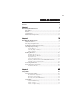
iii TABLE OF CONTENTS Preface i Chapter 1 1 Introducing the Motherboard 1 Introduction............................................................................................1 Feature.....................................................................................................2 Specifications.........................................................................................5 Motherboard Components...................................................................
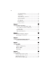
iv Integrated Peripherals.................................................................34 Power Management Setup.............................................................35 PCI/PnP Setup..............................................................................36 PC Health Status..........................................................................37 M.I.B.II (MB Intelligent BIOS II).................................................39 Load Default Settings.......................................
1 Chapter 1 Introducing the Motherboard Introduction Thank you for choosing the A785GM-AD3 motherboard. This motherboard is a high performance, enhanced function motherboard that supports socket for AM3 PhenomTM II/Athlon TM II/ Sempron TM processors for high-end business or personal desktop markets. The motherboard incorporates the AMD 785G Northbridge (NB) and SB710 Southbridge (SB) chipsets. The Northbridge supports the HyperTransportTM 3.0 interface.
2 Feature Processor This • • • motherboard uses a socket AM3 that carries the following features: Accommodates AM3 PhenomTM II/AthlonTM II/ SempronTM processors Supports HyperTransportTM (HT) 3.0 interface speeds Support transfer rate up to 5200 mega-transfers per second HyperTransportTM Technology is a point-to-point link between two devices, it enables integrated circuits to exchange information at much higher speeds than currently available interconnect technologies.
3 Audio • • • • • All DACs support 192K/96K/48K/44.1KHz DAC sample rate High-quality analogy differential CD input Software selectable 2.5V/3.75V VREFOUT Meets Microsoft WLP3.
4 BIOS Firmware The motherboard uses AMI BIOS that enables users to configure many system features including the following: • Power management • Wake-up alarms • CPU parameters • CPU and memory timing The firmware can also be used to set parameters for different processor clock speeds. And it is available to adjust the voltages of the CPU, NB and SB. 1. Some hardware specifications and software items are subject to change without prior notice. 2.
5 Specifications • • • • • • • AM3 socket for PhenomTM II/AthlonTM II/ SempronTM processors Supports “Hyper-Threading” technology CPU Support transfer rate up to 5200 mega-transfers per second AMD 785G & AMD SB710 Dual-channel DDR3 1600 memory architecture 4 x 240-pin DDR3 DIMM sockets support up to 32 GB Supports DDR3 1600/1333/1066/800 DDR3 SDRAM 1 x PCI Express x16 slot 2 x PCI Express x1 slots 3 x PCI slots Storage • • • • • Supported by AMD SB710 Express Chipset 5 x Serial ATA 3.
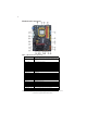
6 Motherboard Components Table of Motherboard Components LABEL COMPONENTS Socket for AM3 PhenomTM II/AthlonTM II/ SempronTM 1. CPU Socket processors CPU cooling fan connector 2. CPU_FAN 240-pin DDR3 SDRAM slots 3. DDR3_1~4 4. ATX_POWER Standard 24-pin ATX power connector 5. IDE Primary IDE connector 6. SPK Speaker header 7. CASE Chassis detector header Serial ATA connectors 8. SATA1~6 Power on button 9. PWR_BTN Front panel switch/LED header 10. F_PANEL Reset button 11.
7 Chapter 2 Installing the Motherboard Safety Precautions • • • • • Follow these safety precautions when installing the motherboard Wear a grounding strap attached to a grounded device to avoid damage from static electricity Discharge static electricity by touching the metal case of a safely grounded object before working on the motherboard Leave components in the static-proof bags they came in Hold all circuit boards by the edges.
8 Do not over-tighten the screws as this can stress the motherboard. Checking Jumper Settings This section explains how to set jumpers for correct configuration of the motherboard. Setting Jumpers Use the motherboard jumpers to set system configuration options. Jumpers with more than one pin are numbered. When setting the jumpers, ensure that the jumper caps are placed on the correct pins. The illustrations show a 2-pin jumper. When the jumper cap is placed on both pins, the jumper is SHORT.
9 Checking Jumper Settings & Clear CMOS Button The following illustration shows the location of the motherboard jumpers. Pin 1 is labeled.
10 Installing Hardware Installing the Processor Caution: When installing a CPU heatsink and cooling fan make sure that you DO NOT scratch the motherboard or any of the surface-mount resistors with the clip of the cooling fan. If the clip of the cooling fan scrapes across the motherboard, you may cause serious damage to the motherboard or its components. On most motherboards, there are small surface-mount resistors near the processor socket, which may be damaged if the cooling fan is carelessly installed.
11 CPU Installation Procedure The following illustration shows CPU installation components. 1 2 3 4 5 Install your CPU. Pull up the lever away from the socket and lift up to 90-degree angle. Locate the CPU cut edge (the corner with the pin hold noticeably missing). Align and insert the CPU correctly. Press the lever down and apply thermal grease on top of the CPU. Put the CPU Fan down on the retention module and snap the four retention legs of the cooling fan into place.
12 Installation Procedure Refer to the following to install the memory modules. 1 2 3 This motherboard supports unbuffered DDR3 SDRAM only. Push the latches on each side of the DIMM slot down. Align the memory module with the slot. The DIMM slots are keyed with notches and the DIMMs are keyed with cutouts so that they can only be installed correctly. Check that the cutouts on the DIMM module edge connector match the notches in the DIMM slot.
13 Table A: DDR3 (memory module) QVL (Qualified Vendor List) The following DDR3 2100/1800/1600/1333/1066 memory modules have been tested and qualified for use with this motherboard. Type Size Vendor Module Name 512 ELPIDA PC3-8500U-7-00-AP HYMT112U64ZNF8-G8 AA Hynix HMT112U6AFP8C-G7N0 AA 1 GB DDR3 1066 Kingston KVR1066D3N7/1G Micron MT8JTF12864AZ-1G1F1 Ramaxel RMR1810NA48E7F-1066-LF Samsung Golden Bar M378B2873DZ1-CF8 0818 Elixir M2Y2G64CB8HA9N-BE 0922.
14 Table B: DDR3 (memory module) QVL (Qualified Vendor List) The following DDR3 2100/1800/1600/1333/1066 memory modules have been tested and qualified for use with this motherboard. Type Size Vendor Module Name A-data AD3U1333B1G9-B Apacer 78.01GC6.
15 Expansion Slots Installing Add-on Cards The slots on this motherboard are designed to hold expansion cards and connect them to the system bus. Expansion slots are a means of adding or enhancing the motherboard’s features and capabilities. With these efficient facilities, you can increase the motherboard’s capabilities by adding hardware that performs tasks that are not part of the basic system. PCIE1~2 Slots The PCI Express x1 slots are fully compliant to the PCI Express Generation 2.0 (version 2.0).
16 Follow these instructions to install an add-on card: 1 2 3 Remove a blanking plate from the system case corresponding to the slot you are going to use. Install the edge connector of the add-on card into the expansion slot. Ensure that the edge connector is correctly seated in the slot. Secure the metal bracket of the card to the system case with a screw.
17 Connecting Optional Devices Refer to the following for information on connecting the motherboard’s optional devices: COM: Onboard serial port header Connect a serial port extension bracket to this header to add a serial port to your system.
18 SATA1~5: Serial ATA connectors These connectors are used to support the new Serial ATA devices for the highest data transfer rates (3.0 Gb/s), simpler disk drive cabling and easier PC assembly. It eliminates limitations of the current Parallel ATA interface. But maintains register compatibility and software compatibility with Parallel ATA.
19 F_USB1~3: Front Panel USB headers The motherboard has six USB ports installed on the rear edge I/O port array. Additionally, some computer cases have USB ports at the front of the case. If you have this kind of case, use auxiliary USB connector to connect the front-mounted ports to the motherboard.
20 Installing a Hard Disk Drive/CD-ROM/SATA Hard Drive This section describes how to install IDE devices such as a hard disk drive and a CDROM drive. About IDE Devices Your motherboard has one IDE interface. An IDE ribbon cable supporting two IDE devices is bundled with the motherboard. You must orient the cable connector so that the pin1 (color) edge of the cable corresponds to the pin 1 of the I/O port connector.
21 Refer to the illustration below for proper installation: 1 2 3 Attach either cable end to the connector on the motherboard. Attach the other cable end to the SATA hard drive. Attach the SATA power cable to the SATA hard drive and connect the other end to the power supply. This motherboard supports the “Hot-Plug” function.
22 Connecting I/O Devices The backplane of the motherboard has the following I/O ports: PS2 Mouse Use the upper PS/2 port to connect a PS/2 pointing device. PS2 Keyboard Use the lower PS/2 port to connect a PS/2 keyboard. VGA Port Connect your monitor to the VGA port. DVI Port Connect the DVI port to connect the monitor. USB Ports Use the USB ports to connect USB devices. ESATA Port Use this port to connect to an external SATA box or a Serial ATA port multiplier.
23 Connecting Case Components After you have installed the motherboard into a case, you can begin connecting the motherboard components. Refer to the following: 1 2 3 4 5 6 7 Connect the CPU cooling fan cable to CPU_FAN. Connect the standard power supply connector to ATX_POWER. Connect the case speaker cable to SPK. Connect the case switches and indicator LEDs to the F_PANEL. Connect the system cooling fan connector to SYS_FAN. Connect the auxiliary case power supply connector to ATX12V1.
24 Connecting 4-pin power cable The ATX12V power connector is used to provide power to the CPU. When installing 4-pin power cable, the latches of power cable and the ATX12V match perfectly. 4-pin power cable CPU_FAN: Cooling FAN Power Connector Pin 1 2 3 4 Function Signal Name GND +12V System Ground Power +12V Sense Sensor PWM CPU FAN control Users please note that the fan connector supports the CPU cooling fan of 1.1A~2.2A (26.4W max.) at +12V.
25 SPK: Internal speaker Pin Signal Name 1 2 3 4 VCC Key NC Signal ATX12V1: ATX 12V Power Connector Pin Signal Name 1 2 3 Ground 4 +12V Ground +12V Front Panel Header The front panel header (F_PANEL) provides a standard set of switch and LED headers commonly found on ATX or Micro ATX cases.
26 Power/Sleep/Message waiting LED Connecting pins 2 and 4 to a single or dual-color, front panel mounted LED provides power on/off, sleep, and message waiting indication. Reset Switch Supporting the reset function requires connecting pin 5 and 7 to a momentarycontact switch that is normally open. When the switch is closed, the board resets and runs POST. Power Switch Supporting the power on/off function requires connecting pins 6 and 8 to a momentary-contact switch that is normally open.
27 Chapter 3 Using BIOS About the Setup Utility The computer uses the latest “American Megatrends Inc. ” BIOS with support for Windows Plug and Play. The CMOS chip on the motherboard contains the ROM setup instructions for configuring the motherboard BIOS. The BIOS (Basic Input and Output System) Setup Utility displays the system’s configuration status and provides you with options to set system parameters.
28 Press the delete key to access the BIOS Setup Utility. CMOS Setup Utility -- Copyright (C) 1985-2005, American Megatrends, Inc. f Standard CMOS Setup f Advanced Setup f Advanced Chipset Setup f Integrated Peripherals f Power Management Setup f PCI/PnP Setup f PC Health Status fM.I.B.
29 Using BIOS When you start the Setup Utility, the main menu appears. The main menu of the Setup Utility displays a list of the options that are available. A highlight indicates which option is currently selected. Use the cursor arrow keys to move the highlight to other options. When an option is highlighted, execute the option by pressing . Some options lead to pop-up dialog boxes that prompt you to verify that you wish to execute that option.
30 For the purpose of better product maintenance, the manufacture reserves the right to change the BIOS items presented in this manual. The BIOS setup screens shown in this chapter are for reference only and may differ from the actual BIOS. Please visit the manufacture’s website for updated manual. Standard CMOS Setup This option displays basic information about your system. CMOS Setup Utility -- Copyright (C) 1985-2005, American Megatrends, Inc.
31 Type (Auto) Use this item to configure the type of the IDE device that you specify. if the feature is unabled, it will enhance hard disk performance by reading or writing more data during each transfer. LBA/Large Mode (Auto) Use this item to set the LAB/Large mode to enhance hard disk performance by optimizing the area the hard disk is visited each time.
32 Advanced Setup This page sets up more advanced information about your system. Handle this page with caution. Any changes can affect the operation of your computer. CMOS Setup Utility - Copyright (C) 1985-2005, American Megatrends, Inc. Advanced Setup AMD C&Q Enhanced Halt (CIE) Quick Power on Self Test Boot Up Numlock Status APIC Mode 1st Boot Device 2nd Boot Device 3rd Boot Device Boot Other Device ECS eJIFFY Function Auto Disabled Enabled ON Enabled Hard Drive CD/DVD Removable Dev.
33 Boot Other Device (Yes) When enabled, the system searches all other possible locations for an operating system if it fails to find one in the devices specified under the First, Second and Third boot devices. ECS eJIFFY Function (Disabled) Use this item to enable or disable the ECS eJIFFY Function. eJIFFY is ECS unique software program for the quick access to the internet without entering O.S. Please refer to Chapter7 to know more about eJIFFY. Press to return to the main menu setting page.
34 Init Display First (PCI) Use this item to select which graphics controller to use as the primary boot devices. Memory Hole Remapping (Enabled) This item allows users to enable or disable memroy hole remapping. HDMI Audio (Enabled) This item is used to enable or disable the onboard audio chip. DCT Unganged Mode (Always) This item is used to select the DCT mode (DRAM Controller mode). Press to return to the main menu setting page.
35 Serial Port1 Address ( Disabled) Use this item to enable or disable the onboard COM1 serial port, and to assign a port address. USB Functions (Enabled) Use this item to enable or disable the USB function. Legacy USB Support (Enabled) Use this item to enable or disable support for legacy USB devices. Setting to Auto allows the system to detect the presence of USB device at startup. If detected, the USB controller legacy mode is enabled. If no USB device is detected, the legacy USB support is disabled.
36 Resume By PCI/PCI-E/Lan PME (Disabled) The system can be turned off with a software command. If you enable this item, the system can automatically resume if there is an incoming call on the PCI Modem or PCI LAN card. You must use an ATX power supply in order to use this feature. Use this item to do wake-up action if inserting the PCI card. Resume By USB (S3) (Disabled) This item allows you to enable/disable the USB device wakeup function from S3 mode.
37 PC Health Status On motherboards support hardware monitoring, this item lets you monitor the parameters for critical voltages, temperatures and fan speeds. CMOS Setup Utility - Copyright (C) 1985-2005 , American Megatrends, Inc.
38 Smart Fan Mode (Normal) This item allows you to select the fan mode (Normal, Quiet, Silent, or Manual) for a better operation environment. If you choose Normal mode, the fan speed will be auto adjusted depending on the CPU temperature. If you choose Quite mode, the fan speed will be auto minimized for quiet environment. If you choose Silent mode, the fan speed will be auto restricted to make system more quietly. If you choose Manual mode, the fan speed will be adjust depending on users’ parameters.
39 M.I.B. II (MB Intelligent BIOS II) This page enables you to set the clock speed and system bus for your system. The clock speed and system bus are determined by the kind of processor you have installed in your system. CMOS Setup Utility - Copyright (C) 1985-2005, American Megatrends, Inc. M.I.B.
40 DRAM Frequency (Auto) This item enables users to adjust the DRAM frequency. The default setting is auto and we recommend users leave the setting unchanged. Modify it at will may cause the system to be unstable. DRAM Timing Mode (Auto) This item enables you to specify the DRAM timing mode to be configured automatically or manually. Bank Interleaving (Auto) This item is used to set the bank interleaving. Channel Interleaving (XOR of Address bits) This item is used to set the channel interleaving.
41 HT Frequency (Auto) This item enables users to adjust the HT frequency. The default setting is auto and we recommend users leave the setting unchanged. Modify it at will may cause the system to be unstable. CPU/HT Reference Clock (MHz) (200) Use this item to set the CPU/HT Reference Clock through clock gen. Auto Detect DIMM/PCI Clk (Enabled) When this item is enabled, BIOS will disable the clock signal of free DIMM/PCI slots.
42 NB Voltage Default (1.15v) This item indicates the NB voltage default value. SB Voltage Default (1.20v) This item indicates the SB voltage default value. Press to return to the main menu setting page. Load Default Settings This option opens a dialog box to ask if you are sure to install optimized defaults or not. You select [OK], and then press , the Setup Utility loads all default values; or select [Cancel], and then press , the Setup Utility does not load default values.
43 User Password This page helps you install or change a password. CMOS Setup Utility - Copyright (C) 1985-2005, American Megatrends, Inc. User Password User Password : Not Installed Change User Password Help item Press Enter mnlk: Move Enter : Select +/-/: Value F10: Save F1:General Help F9: Default settings Install or Change the password. ESC: Exit User Password (Not Installed) This item indicates whether a user password has been set. If the password has been installed, Installed displays.
44 Updating the BIOS You can download and install updated BIOS for this motherboard from the manufacturer’s Web site. New BIOS provides support for new peripherals, improvements in performance, or fixes for known bugs. Install new BIOS as follows: 1 If your motherboard has a BIOS protection jumper, change the setting to allow BIOS flashing. 2 If your motherboard has an item called Firmware Write Protect in Advanced BIOS features, disable it. (Firmware Write Protect prevents BIOS from being overwritten.
45 Chapter 4 Using the Motherboard Software About the Software DVD-ROM/CD-ROM The support software DVD-ROM/CD-ROM that is included in the motherboard package contains all the drivers and utility programs needed to properly run the bundled products. Below you can find a brief description of each software program, and the location for your motherboard version. More information on some programs is available in a README file, located in the same directory as the software.
46 Drivers Tab Setup Click the Setup button to run the software installation program. Select from the menu which software you want to install. Browse CD The Browse CD button is the standard Windows command that allows you to open Windows Explorer and show the contents of the support disk. Before installing the software from Windows Explorer, look for a file named README.TXT or something similar. This file may contain important information to help you install the software correctly.
47 2. Click Next. The following screen appears: 3. Check the box next to the items you want to install. The default options are recommended. 4. Click Next run the Installation Wizard. An item installation screen appears: 5. Follow the instructions on the screen to install the items. Drivers and software are automatically installed in sequence. Follow the onscreen instructions, confirm commands and allow the computer to restart a few times to complete the installation.
48 Windows Vista/7 will appear below UAC (User Account Control) message after the system restart. You must select “Allow” to install the next driver. Continue this process to complete the drivers installation. Manual Installation Insert the disk in the DVD-ROM/CD-ROM drive and locate the PATH.DOC file in the root directory. This file contains the information needed to locate the drivers for your motherboard.
49 Chapter 5 Hybrid Graphics®Technology Support Hybrid Graphics®Technology The Hybrid Graphics ® technology provides significant display performance boost to AMD-based systems by inserting the external PCI Express graphics card and enabling both the discrete GPU and the AMD785G graphics core to render simultaneously in Hybrid CrossFireTM mode. Follow the steps below to start the Hybrid Graphics® technology. 1.
50 SurroundView TM provides the power and convenience of multiadapter, multimonitor support for computers that use a PCI-Express based graphics card in conjunction with ATI integrated graphic processors. And there are two options: Disabled and PCI Express. If SurroundView TM set to Disabled, and Init Display First set to OnBoard, SurroundViewTM will be Enabled by Catalyst Control Center based on cancel the Enable CrossFireTM option.
51 4. Enter Catalyst Control Center, you can see the option of CrossFireTM, click it and select Enable CrossFireTM, then Hybrid Graphics® starts. To disable Hybrid Graphics®, please make sure to cancel Enable CrossFireTM in Catalyst Control Center firstly.
52 Memo Hybrid Graphics®Technology Support
53 Chapter 6 Setting Up AMD SB710 RAID Configuration Setting Up a bootable RAID Array This section explains how to configure a bootable AMD RAID array. Setting Up the BIOS 1 Start your computer, then press Delete to enter the BIOS setup. The BIOS CMOS Setup Utility screen appears. Figure 1.1 2 BIOS CMOS Setup Utility Main Screen Use the arrow keys to select Integrated Peripherals (see Figure 1.1), then press Enter. The Integrated Peripherals screen (or a screen similar to it) appears. Figure 1.
54 4 Press F10 to save the configuration and exit. The PC reboots. 5 Enter the RAID BIOS Setup by pressing Ctrl-F when prompted, and proceed to set up the AMD RAID BIOS as described in the next section. Configuring the AMD RAID BIOS The AMD RAID BIOS set up lets you choose the RAID type and which hard drives you want to make part of the array. Entering the RAID BIOS Setup: 1 Wait until you see the RAID software prompting you to press Ctrl-F.
55 3 Select [2], then select LD 1 in the following page. The Define LD Menu screen appears (Figure 1.4). Figure 1.4 Define LD Menu Using the Define a New Array Screen If necessary, press the tab key to move from field to field until the appropriate field is highlighted. • Selecting the RAID Mode By default, this is set to Mirroring. To change to a different RAID mode, press the spacebar until the mode that you want appears in the RAID Mode box—RAID0/1/10/JBOD.
56 Assigning the Disks 1. Select the Assignment to Y to designate a free disk to be used as a RAID array disk. Figure 1.5 illustrates the Define a New Array screen after two disks have been assigned as RAID 0 array disks. Figure 1.5 FastBuild Utility—Array Disks Assigned 2. Press Ctrl-Y to save the configuration and exit. The Define LD Menu screen appears (Figure 1.6). Figure 1.
57 3. Press ESC to exit. The Main Menu screen appears (Figure 1.7). Figure 1.7 4 Main Menu Press Y to reboot. The following screen appears (Figure 1.8). Figure 1.
58 Installing the RAID Drivers Your system may come with a Windows install CD that already includes AMD RAID drivers. If so, then this section is not relevant. If that is not the case (or you are trying to install a new version of Windows), then you will need an AMD RAID driver F6 install floppy. Check to see if one came with your system. If not, you can create one by downloading the appropriate driver package and following the steps in this section. 1 2 Copy all files in "...
59 The following Windows Setup screen appears: Figure 1.11 Windows Setup—Selected SCSI Adapter b Select “ATI AHCI Compatible RAID Controller-x86 platform” and press Enter for 32-bit OS or Select “ATI AHCI Compatible RAID Controller-x64 platform” and press Enter for 64-bit OS. The following Windows Setup screen appears listing both drivers:. Figure 1.12 Windows Setup—AMD drives listed 5 Press Enter to continue with Windows XP Installation.
60 Memo AMD RAID Configuration
61 Chapter 7 Setting Up eJIFFY Introduction eJIFFY is a fast boot program under Linux. Instead of waiting Windows O.S to start execution, eJIFFY is ready to provide users the instant enjoyment on web browsing, photo review and online chat just within several seconds after boot up. Note: eJIFFY is ECS optional feature utility corresponding to the DVD activation and BIOS setup. Please check the hard copy user’s guide or product color-box to see if the model has embodded eJIFFY feature.
62 Installation and BIOS Setup DVD Activation Finish the DVD utility setup, and then set the BIOS to complete eJIFFY activation. 1. Insert ECS software utility DVD and enter below “Utilities” screen. Click eJIFFY feature item to install. 2. Follow the onscreen instructions to finish eJIFFY setup.
63 3. After setting up eJIFFY under Windows, you can switch eJIFFY display/keyboard language from English to your local language. The changes will be applied after rebooting. Note: The keyboard language selection list offers several more regional keyboard setups to switch with the default English typing. Please refer to the usage FAQ for more tips.
64 4. Restart your computer after eJIFFY installation. Press or click the BIOS Setup button on the post screen to enter the BIOS setup page after boot up. 5. And then enter the Advanced Setup page to enable the item ECS eJIFFY Function. Press F10 to save the configuration and exit. Restart your computer. Note: 1. eJIFFY is available in SATA/IDE/AHCI mode. It does not support RAID configuration and the onboard 34-pin floppy drives. 2. Please refer to ECS website for new eJIFFY application updates.
65 Entering eJIFFY The post screen appears within several seconds after boot up and it has three buttons on it, Operating system, eJIFFY and BIOS Setup. Click to enter the normal OS you have installed such as Windows. Click to enter eJIFFY OS. Click to set the BIOS. If you click eJIFFY, the following screen will appear. And If you make no choice it will enter the normal OS automatically after ten seconds.
66 Feature Icons The following illustration shows the main feature icons that eJIFFY provides on the menu. eWeb: Firefox for web browsing/webmail and watching flash video. ePix: Photo viewing. ePal: On-line chat tool to use the most popular IMs in the world. (MSN, ICQ , AIM, etc.) Shows ePal on-line connection status. Shut Down/Restart: Ends your session and turns off the computer./Ends your session and restart the computer.. Click once to connect the storage disk to your computer.
67 Usage FAQ Language Control Panel: Besides setting English as the default interface, eJIFFY offers multi-language displays and keyboard settings for languageswitch. Open the language control panel to select a preferable language setting. Keyboard Language Setup Step1. Click to open the language control panel.
68 Step 2: Click “Keyboard Language” icon to open the keyboard selection list, which offers several regional keyboard settings besides default English keyboard. Step 3: Click the selected keyboard language (e.g. French) and press “OK”.
69 Tips for Language Switch: Tip 1: Click “Change Keyboard” icon to switch the typing language. The typing language on text box will switch to the selected one: Click again to switch to English typing back. Tip 2. If you use the default English keyboard, eJIFFY still offers other language inputs to switch with English.
70 Setting Up eJIFFY
71 Setting Up eJIFFY
72 Tip 3. How to change display language? Open the Language Control Panel and click to show the display language list. Check your desired display language. Your selected display language will be applied after rebooting.
73 eWeb: Firefox for web browsing/webmail and watching flash video. Q1: How to download files to hard disk through eWeb? Click on the file link directly. Then select “Save File” in the pop-up window. Note: 1. Before downloading files, please “mount” the storage devices to make sure the device is connected with eJIFFY interface. (Please refer to the usage FAQ to mount devices) 2. eWeb does not support Office Viewer/Reader/Writer format under eJIFFY interface.
74 Q2: How to save image file through eWeb? 1. Select the image you want to save and press the right key of your mouse to show the menu, then click the option “ Save Image As” from the menu. 2. Then the “Save Image” window appears. You may rename the image file in the “Name” column and save the file in a folder as the following picture shows. Rename the image file. Then select a subdirectory or click “Create Folder” to create a new folder. Select a root directory. Click here to save the image file.
75 ePix: Photo viewing. Q1: How to find image files saved in hard disk through ePix? Enter the ePix window, then click the icon “Folder” located in the upper left-hand corner, then follow the path for the files you have saved to view the image files.
76 Q2: How to use the fit function under slide show? 1. Click “Edit” and select “Preferences” option from the menu. 2. Click “Viewer” and choose “Keep previous zoom” in “After loading an image”. Close the window and you can use the fit function under slide show now. Note: ePix supports to view image files only. It cannot support Office Viewer or other forms beside image files. Supported image types are: BMP, JPEG, GIF (including GIF animations), PNG, TIFF, ICO and XPM.
77 Mount/Unmount Disk. Q1: What does it mean for “Mount Disk”? “Mount” means to connect the storage devices to eJIFFY interface. After plugging the external device to the computer such as USB drives, a new disk icon will appear as the following picture shows. Please click the “mount” prompt on the icon. It will change to to show the device is detected successfully. Q2: What does it mean for “Unmount Disk”? “Unmount” is to safely remove the storage devices.
78 Memo Setting Up eJIFFY
79 Chapter 8 Trouble Shooting Start up problems during assembly After assembling the PC for the first time you may experience some start up problems. Before calling for technical support or returning for warranty, this chapter may help to address some of the common questions using some basic troubleshooting tips. a) System does not power up and the fans are not running. 1.Disassemble the PC to remove the VGA adaptor card, DDR memory, LAN, USB and other peripherals including keyboard and mouse.
80 c) The PC suddenly shuts down while booting up. 1. The CPU may experience overheating so it will shutdown to protect itself. Ensure the CPU fan is working properly. 2. From the BIOS setting, try to disable the Smartfan function to let the fan run at default speed. Doing a Load Optimised Default will also disable the Smartfan. Start up problems after prolong use After a prolong period of use your PC may experience start up problems again.
If fail, contact RMA CLR CMOS and restart. Yes Halt at POST screen? Yes Check if monitor has display Yes Check if Power Supply Unit (PSU) is working Power Bu on is pressed but PC fails to start. CMOS setup error, - need to CLRCMOS. HDD problem.
82 Memo Trouble Shooting