Preface Copyright This publication, including all photographs, illustrations and software, is protected under international copyright laws, with all rights reserved. Neither this manual, nor any of the material contained herein, may be reproduced without written consent of the author. Version 1.0 Disclaimer The information in this document is subject to change without notice.
ii Declaration of Conformity This device complies with part 15 of the FCC rules. Operation is subject to the following conditions: • • This device may not cause harmful interference, and This device must accept any interference received, including interference that may cause undesired operation. Canadian Department of Communications This class B digital apparatus meets all requirements of the Canadian Interferencecausing Equipment Regulations.
iii TABLE OF CONTENTS Preface i Chapter 1 1 Introducing the Motherboard 1 Introduction............................................................................................1 Features...................................................................................................2 Motherboard Components...................................................................4 Chapter 2 7 Installing the Motherboard 7 Safety Precautions.................................................................
iv Load Default Settings....................................................................42 Supervisor Password.....................................................................42 User Password...............................................................................43 Save & Exit Setup ..........................................................................43 Exit Without Saving........................................................................43 Updating the BIOS........................
1 Chapter 1 Introducing the Motherboard Introduction Thank you for choosing the A890GXM-A motherboard. This motherboard is a high performance, enhanced function motherboard that supports socket for AMD PhenomTM II/AthlonTM II/SempronTM processors (socket AM3) for high-end business or personal desktop markets. The motherboard incorporates the AMD 890GX Northbridge (NB) and SB850 Southbridge (SB) chipsets. The Northbridge supports the HyperTransportTM 3.0 interface.
2 Feature Processor This motherboard uses a socket AM3 that carries the following features: • • Accommodates AMD PhenomTM II/AthlonTM II/SempronTM processors (socket AM3) Supports HyperTransportTM (HT) 3.0 interface speeds HyperTransportTM Technology is a point-to-point link between two devices, it enables integrated circuits to exchange information at much higher speeds than currently available interconnect technologies.
3 Audio • • 7.1+2 Channel High Definition Audio Codec Meets Microsoft WLP3.x (Windows Logo Program) audio requirements All DACs supports 44.1k/48k/96k/192kHz sample rate Software selectable 2.5V/3.2V/4.0V VREFOUT Direct Sound 3D. compatible Power Support: Digital: 3.3V; Analog: 5.0V • • • • Onboard LAN Supports PCI ExpressTM 2.
4 Specifications • AMD PhenomTM II/AthlonTM II/SempronTM processors (socket AM3) Supports “Hyper-Threading” technology CPU Chipset • NB: AMD 890GX SB: SB850 Memory • • • Dual-channel DDR3 memory architecture 4 x 240-pin DDR3 DIMM sockets support up to 32 GB Supports DDR3 1600 (OC)/1333/1066/800 DDR3 SDRAM Expansion Slots • • • • 2 x PCI Express Gen2 x16 slots 1 x PCI Express x4 slot(the blue PCI Express x16 is bandwidth of x4) 2 x PCI Express x1 slots 1 x PCI slot Storage • • • Supported by AM
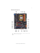
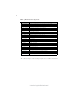
5 Motherboard Components The above image is for reference only; please take the actual motherboard for detailed parts.
6 Table of Motherboard Components LABEL 1. CPU Socket 2. CPU_FAN 3. DDR3_1~4 4. ATX_POW ER 5. PW R_FAN 6. CASE 7. SATA1~5 8. SPK 9. SPI_DEBUG 10. F_PANEL 11. PW R_BTN 12. RST_BTN 13. F_USB1~4 14. SYS_FAN 15. SPDIFO 16. F_AUDIO 17. PCI 18. PCIE16X_T 19. PCIE16X_S 20. PCIE1~2 21. PCIEX16 22. ATX4P 23.
7 Chapter 2 Installing the Motherboard Safety Precautions • • • • • Follow these safety precautions when installing the motherboard Wear a grounding strap attached to a grounded device to avoid damage from static electricity Discharge static electricity by touching the metal case of a safely grounded object before working on the motherboard Leave components in the static-proof bags they came in Hold all circuit boards by the edges.
8 Do not over-tighten the screws as this can stress the motherboard. Installing Hardware Installing the Processor Caution: When installing a CPU heatsink and cooling fan make sure that you DO NOT scratch the motherboard or any of the surface-mount resistors with the clip of the cooling fan. If the clip of the cooling fan scrapes across the motherboard, you may cause serious damage to the motherboard or its components.
9 Before installing the Processor This motherboard automatically determines the CPU clock frequency and system bus frequency for the processor. You may be able to change these settings by making changes to jumpers on the motherboard, or changing the settings in the system Setup Utility. We strongly recommend that you do not over-clock processors or other components to run faster than their rated speed. Warning: 1.
10 CPU Installation Procedure The following illustration shows CPU installation components. 1 2 3 4 5 Install your CPU. Pull up the lever away from the socket and lift up to 90-degree angle. Locate the CPU cut edge (the corner with the pin hold noticeably missing). Align and insert the CPU correctly. Press the lever down and apply thermal grease on top of the CPU. Put the CPU Fan down on the retention module and snap the four retention legs of the cooling fan into place.
11 Installation Procedure Refer to the following to install the memory modules. 1 2 3 4 5 6 This motherboard supports unbuffered DDR3 SDRAM only. Push the latches on each side of the DIMM slot down. Align the memory module with the slot. The DIMM slots are keyed with notches and the DIMMs are keyed with cutouts so that they can only be installed correctly. Check that the cutouts on the DIMM module edge connector match the notches in the DIMM slot.
12 Table A: DDR3 (memory module) QVL (Qualified Vendor List) The following DDR3 memory modules have been tested and qualified for use with this motherboard. Type Size 1 GB Vendor Module Name Hynix HMT112U6AFP8C-G7N0 AA Kingston KVR1066D3N7 Micron MT8JTF12864AZ-1G1F1 Ramaxel RMR1810NA48E7F-1066-LF M2Y2G64CB8HC9N-BE Elixir DDR3 1066 M2Y2G64CB8HC5N-BE M2Y2G64CB8HA9N-BE 0922.TW 2 GB Kingston Micron KVR1066D3N7/4G 9905403-028.
13 Table B: DDR3 (memory module) QVL (Qualified Vendor List) The following DDR3 memory modules have been tested and qualified for use with this motherboard. Type Size Vendor Module Name A-data AD3U1333B2G9-B Apacer 78.A1GC6.9L1 M2F2G64CB8HA4N-CG 0903.TW Elixir M2Y2G64CB8HC9N-CG EBJ21UE8BDF0-DJ-F/J1108BDSE-DJ-F M2Y2G64CB8HA9N-CG 0920.TW F3-10666CL9D-4GBRL G.
14 Expansion Slots Installing Add-on Cards The slots on this motherboard are designed to hold expansion cards and connect them to the system bus. Expansion slots are a means of adding or enhancing the motherboard’s features and capabilities. With these efficient facilities, you can increase the motherboard’s capabilities by adding hardware that performs tasks that are not part of the basic system. PCIE1~2 Slots The PCI Express x1 slots are fully compliant to the PCI Express Gen2 (version 2.0).
15 Follow these instructions to install an add-on card: 1 2 3 Remove a blanking plate from the system case corresponding to the slot you are going to use. Install the edge connector of the add-on card into the expansion slot. Ensure that the edge connector is correctly seated in the slot. Secure the metal bracket of the card to the system case with a screw. * For reference only Notice to User: 1. When use some add-on cards on this motherboard, please install the required driver and software first. 2.
16 Connecting Optional Devices Refer to the following for information on connecting the motherboard’s optional devices: SATA1~5: Serial ATA connectors These connectors are used to support the new Serial ATA devices for the highest data transfer rates (6.0 Gb/s), simpler disk drive cabling and easier PC assembly. It eliminates limitations of the current Parallel ATA interface. But maintains register compatibility and software compatibility with Parallel ATA.
17 F_USB1~4: Front Panel USB headers The motherboard has six USB ports installed on the rear edge I/O port array. Additionally, some computer cases have USB ports at the front of the case. If you have this kind of case, use auxiliary USB connector to connect the front-mounted ports to the motherboard.
18 Installing a SATA Hard Drive This section describes how to install a SATA hard drive. About SATA Connectors Your motherboard features five SATA connectors supporting a total of four drives. SATA refers to Serial ATA (Advanced Technology Attachment) is the standard interface for the IDE hard drives which are currently used in most PCs. These connectors are well designed and will only fit in one orientation.
19 Connecting I/O Devices The backplane of the motherboard has the following I/O ports: VGA Port Connect your monitor to the VGA port. DVI Port Use the DVI port to connect the monitor. DIS Port(Dispaly Port) Use the Display port to connect the monitor. HDMI Port Connect the HDMI port to the HDMI devices. CLR_COMS_BTN Use the CLR_CMOS button to clear CMOS. USB Ports Use the USB ports to connect USB devices. LAN Port Connect an RJ-45 jack to the LAN port to connect your computer to the network.
20 Connecting Case Components After you have installed the motherboard into a case, you can begin connecting the motherboard components. Refer to the following: 1 Connect the CPU cooling fan cable to CPU_FAN. 2 Connect the standard power supply connector to ATX_POWER. 3 Connect the case speaker cable to SPK. 4 Connect the case switches and indicator LEDs to the PANEL. 5 Connect the system cooling fan connector to SYS_FAN. 6 Connect the auxiliary case power supply connector to ATX12V.
21 Connecting 8/4-pin power cable Users please note that the 8-pin and 4-pin power cables can both be connected to the ATX12V connector. When installing 8-pin power cable, the latches of power cable and the ATX12V connector match perfectly. 8-pin power cable When installing 4-pin power cable, the latch falls on the left side of the ATX12V connector.
22 SYS_FAN: FAN Power Connector Pin 1 2 3 Signal Name Function System Ground Power +12V Sensor GND +12V Sense SPK: Internal speaker Pin 1 2 3 4 Signal Name VCC Key NC Signal ATX12V: ATX 12V Power Connector Pin Signal Name Pin 1 2 3 4 Ground 5 6 7 8 Ground Ground Ground Signal Name +12V +12V +12V +12V ATX4P: Auxliary Power Connector for Graphics Interface.
23 Front Panel Header The front panel header (F_PANEL) provides a standard set of switch and LED headers commonly found on ATX or Micro ATX cases.
24 Memo Installing the Motherboard
25 Chapter 3 Using BIOS About the Setup Utility The computer uses the latest “American Megatrends Inc. ” BIOS with support for Windows Plug and Play. The CMOS chip on the motherboard contains the ROM setup instructions for configuring the motherboard BIOS. The BIOS (Basic Input and Output System) Setup Utility displays the system ’ s configuration status and provides you with options to set system parameters.
26 Press the delete key to access the BIOS Setup Utility. CMOS Setup Utility -- Copyright (C) 1985-2005, American Megatrends, Inc. f Standard CMOS Setup f Advanced Setup f Advanced Chipset Setup f Integrated Peripherals f Power Management Setup f PCI/PnP Setup f PC Health Status f M.I.B.
27 Using BIOS When you start the Setup Utility, the main menu appears. The main menu of the Setup Utility displays a list of the options that are available. A highlight indicates which option is currently selected. Use the cursor arrow keys to move the highlight to other options. When an option is highlighted, execute the option by pressing . Some options lead to pop-up dialog boxes that prompt you to verify that you wish to execute that option.
28 For the purpose of better product maintenance, the manufacture reserves the right to change the BIOS items presented in this manual. The BIOS setup screens shown in this chapter are for reference only and may differ from the actual BIOS. Please visit the manufacture’s website for updated manual. Standard CMOS Setup This option displays basic information about your system. CMOS Setup Utility -- Copyright (C) 1985-2005, American Megatrends, Inc.
29 Type (Auto) Use this item to configure the type of the IDE device that you specify. If the feature is enabled, it will enhance hard disk performance by reading or writing more data during each transfer. LBA/Large Mode (Auto) Use this item to set the LBA/Large mode to enhance hard disk performance by optimizing the area the hard disk is visited each time.
30 Advanced Setup This page sets up more advanced information about your system. Handle this page with caution. Any changes can affect the operation of your computer. CMOS Setup Utility - Copyright (C) 1985-2005, American Megatrends, Inc.
31 f Hard Disk Drive Priority (Press Enter) Scroll to this item and press < Enter > to view the following screen: CMOS SETUP UTILITY Hard Disk Drive Priority Help Item Hard Disk Drive Priority 1st Drive mnlk : Move F1:General Help [ HDD: PO-WDC WD800JD1] Enter : Select +/-/: Value F9: Load Default Settings Specifies the boot sequence from the available devices. F10: Save & Exit Setup ESC: Exit Without Saving Press to return to the Advanecd BIOS Features page.
32 Advanced Chipset Setup This page sets up more advanced information about your system. Handle this page with caution. Any changes can affect the operation of your computer. CMOS Setup Utility - Copyright (C) 1985-2005, American Megatrends, Inc.
33 Integrated Peripherals This page sets up some parameters for peripheral devices connected to the system. CMOS Setup Utility - Copyright (C) 1985-2005, American Megatrends, Inc. Integrated Peripherals Help Item Onboard SATA Mode SATA Configuration SATA 6.
34 Power Management Setup This page sets up some parameters for system power management operation. CMOS Setup Utility - Copyright (C) 1985-2005, American Megatrends, Inc. Power Management Setup ACPI Suspend Type PWRON After PWR-Fail Resume By PCI/PCI-E/Lan PME Resume By USB (S3) EUP Support mnlk: Move S3 Power Off Disabled Disabled Enabled Enter : Select F1:General Help +/-/: Value F10: Save F9: Optimized Defaults Help Item Select the ACPI state used for System Suspend.
35 PCI / PnP Setup This page sets up some parameters for devices installed on the PCI bus and those utilizing the system plug and play capability. CMOS Setup Utility - Copyright (C) 1985-2005, American Megatrends, Inc. PCI / PnP Setup Help Item Allocate IRQ to PCI VGA Yes YES: Assigns IRQ to PCI VGA card if card requests IRQ. NO: Does not assign IRQ to PCI VGA card even if card requests an IRQ.
36 f Smart Fan Function Scroll to this item and press to view the following screen: CMOS Setup Utility - Copyright (C) 1985-2005, American Megatrends, Inc. Smart Fan Function Help Item SMART FAN Control SMART Fan Mode SMART Fan start PWM value SMART Fan start TEMP.
37 CMOS Setup Utility - Copyright (C) 1985-2005, American Megatrends, Inc. Smart Fan Function Help Item SMART FAN Control SMART Fan Mode SMART Fan start PWM value SMART Fan start TEMP.(°C) DeltaT1 SMART Fan Slope PWM value CPU FAN Full Limit Temp Enabled Normal 144 52 +3 8 PWM value/°C 65°C SMART Fan2 Control Disabled mnlk: Move Enter : Select F1:General Help Normal: auto adjusts depending on the CPU temperture Quiet: auto minimizes fan speed for quiet environment operation.
38 System Component Characteristics These items display the monitoring of the overall inboard hardware health events, such as System & CPU temperature, CPU & DIMM voltage, CPU & system fan speed,...etc. • • • • • • CPU Temperature NB Temperature CPU FAN Speed CPU Vcore VDIMM NB Voltage Press to return to the main menu setting page.
39 M.I.B. III (MB Intelligent BIOS III) This page enables you to set the clock speed and system bus for your system. The clock speed and system bus are determined by the kind of processor you have installed in your system. CMOS Setup Utility - Copyright (C) 1985-2005, American Megatrends, Inc. M.I.B.III (MB Intelligent BIOS III) f Memory Configuration Press Enter Auto Auto 200 Enabled Enabled Disabled Disabled Disabled Disabled 1.
40 Bank Interleaving (Auto) This item is used to set the bank interleaving. Channel Interleaving (XOR of Address bits) This item is used to set the channel interleaving. Memory CLK (N/A, 667MHz) This item is used to set the memory clock mode. CAS Latency (Tcl) (N/A, 9Clk) This item controls the timing delay (inclockcycles) before the DRAM starts a read command after receiving it. RAS/CAS Delay (Trcd) (N/A, 9Clk) This is the amount of time a CAS is performed after a RAS.
41 NB Voltage (Disabled) This item allows user to adjust NB voltage when enabled. HT Voltage (Disabled) This item allows user to adjust HT voltage when enabled. SB Voltage (Disabled) This item allows user to adjust SB voltage when enabled. SIDEPORT Voltage (1.5V) This item allows user to adjust sideport voltage when enabled. AMD Phenom (tm) II X3 750e Processor Speed (2500MHz) This is display-only field and displays the information of the CPU installed in your computer.
42 Load Default Settings This option opens a dialog box to ask if you are sure to install optimized defaults or not. You select [OK], and then press , the Setup Utility loads all default values; or select [Cancel], and then press , the Setup Utility does not load default values. Supervisor Password This page helps you install or change a password. CMOS Setup Utility - Copyright (C) 1985-2005, American Megatrends, Inc.
43 User Password This page helps you install or change a password. CMOS Setup Utility - Copyright (C) 1985-2005, American Megatrends, Inc. User Password User Password : Not Installed Help item mnlk: Move Enter : Select +/-/: Value F10: Save ESC: Exit F1:General Help F9: Optimized Defaults User Password (Not Installed) This item indicates whether a user password has been set. If the password has been installed, Installed displays. If not, Not Installed displays.
44 Updating the BIOS You can download and install updated BIOS for this motherboard from the manufacturer’s Web site. New BIOS provides support for new peripherals, improvements in performance, or fixes for known bugs. Install new BIOS as follows: 1 If your motherboard has a BIOS protection jumper, change the setting to allow BIOS flashing. 2 If your motherboard has an item called Firmware Write Protect in Advanced BIOS features, disable it. (Firmware Write Protect prevents BIOS from being overwritten.
45 Chapter 4 Using the Motherboard Software About the Software DVD-ROM/CD-ROM The support software DVD-ROM/CD-ROM that is included in the motherboard package contains all the drivers and utility programs needed to properly run the bundled products. Below you can find a brief description of each software program, and the location for your motherboard version. More information on some programs is available in a README file, located in the same directory as the software.
46 Drivers Click the Setup button to run the software installation program. Select from the menu which software you want to install. Setup Browse CD The Browse CD button is the standard Windows command that allows you to open Windows Explorer and show the contents of the support disk. Before installing the software from Windows Explorer, look for a file named README.TXT or something similar. This file may contain important information to help you install the software correctly.
47 2. Click Next. The following screen appears: 3. Check the box next to the items you want to install. The default options are recommended. 4. Click Next run the Installation Wizard. An item installation screen appears: 5. Follow the instructions on the screen to install the items. Drivers and software are automatically installed in sequence. Follow the onscreen instructions, confirm commands and allow the computer to restart a few times to complete the installation.
48 Windows Vista/7 will appear below UAC (User Account Control) message after the system restart. You must select “Allow” to install the next driver. Continue this process to complete the drivers installation. Manual Installation Insert the disk in the DVD-ROM/CD-ROM drive and locate the PATH.DOC file in the root directory. This file contains the information needed to locate the drivers for your motherboard.
49 Chapter 5 Setting Up AMD SB850 RAID Configuration Setting Up a bootable RAID Array This section explains how to configure a bootable AMD RAID array. Setting Up the BIOS 1 Start your computer, then press Delete to enter the BIOS setup. The BIOS CMOS Setup Utility screen appears. Figure 1.1 2 BIOS CMOS Setup Utility Main Screen Use the arrow keys to select Integrated Peripherals (see Figure 1.1), then press Enter. The Integrated Peripherals screen (or a screen similar to it) appears. Figure 1.
50 4 Press F10 to save the configuration and exit. The PC reboots. 5 Enter the RAID BIOS Setup by pressing Ctrl-F when prompted, and proceed to set up the AMD RAID BIOS as described in the next section. Configuring the AMD RAID BIOS The AMD RAID BIOS set up lets you choose the RAID type and which hard drives you want to make part of the array. Entering the RAID BIOS Setup: 1 Wait until you see the RAID software prompting you to press Ctrl-F.
51 3 Select [2], then select LD 1 in the following page. The Define LD Menu screen appears (Figure 1.4). Figure 1.4 Define LD Menu Using the Define a New Array Screen If necessary, press the tab key to move from field to field until the appropriate field is highlighted. • Selecting the RAID Mode By default, this is set to Mirroring. To change to a different RAID mode, press the spacebar until the mode that you want appears in the RAID Mode box—RAID0/1/10/JBOD.
52 Assigning the Disks 1. Select the Assignment to Y to designate a free disk to be used as a RAID array disk. Figure 1.5 illustrates the Define a New Array screen after two disks have been assigned as RAID 0 array disks. Figure 1.5 FastBuild Utility—Array Disks Assigned 2. Press Ctrl-Y to save the configuration and exit. The Define LD Menu screen appears (Figure 1.6). Figure 1.
53 3. Press ESC to exit. The Main Menu screen appears (Figure 1.7). Figure 1.7 4 Main Menu Press Y to reboot. The following screen appears (Figure 1.8). Figure 1.
54 Installing the RAID Drivers Your system may come with a Windows install CD that already includes AMD RAID drivers. If so, then this section is not relevant. If that is not the case (or you are trying to install a new version of Windows), then you will need an AMD RAID driver F6 install floppy. Check to see if one came with your system. If not, you can create one by downloading the appropriate driver package and following the steps in this section. 1 Copy all files in "...
55 The following Windows Setup screen appears: Figure 1.11 Windows Setup—Selected SCSI Adapter b Select “ATI AHCI Compatible RAID Controller-x86 platform” and press Enter for 32-bit OS or Select “ATI AHCI Compatible RAID Controller-x64 platform” and press Enter for 64-bit OS. The following Windows Setup screen appears listing both drivers:. Figure 1.12 Windows Setup—AMD drives listed 5 Press Enter to continue with Windows XP Installation.
56 Memo AMD RAID Configuration
57 Chapter 6 Setting Up eJIFFY Introduction eJIFFY is a fast boot program under Linux. Instead of waiting Windows O.S to start execution, eJIFFY is ready to provide users the instant enjoyment on web browsing, photo review and online chat just within several seconds after boot up. Note: eJIFFY is ECS optional feature utility corresponding to the DVD activation and BIOS setup. Please check the hard copy user’s guide or product color-box to see if the model has embodded eJIFFY feature.
58 Installation and BIOS Setup DVD Activation Finish the DVD utility setup, and then set the BIOS to complete eJIFFY activation. 1. Insert ECS software utility DVD and enter below “Utilities” screen. Click eJIFFY feature item to install. 2. Follow the onscreen instructions to finish eJIFFY setup.
59 3. After setting up eJIFFY under Windows, you can switch eJIFFY display/keyboard language from English to your local language. The changes will be applied after rebooting. Note: The keyboard language selection list offers several more regional keyboard setups to switch with the default English typing. Please refer to the usage FAQ for more tips.
60 4. Restart your computer after eJIFFY installation. Press or click the BIOS Setup button on the post screen to enter the BIOS setup page after boot up. 5. And then enter the Advanced Setup page to enable the item ECS eJIFFY Function. Press F10 to save the configuration and exit. Restart your computer. Note: 1. eJIFFY is available in SATA/IDE/AHCI mode. It does not support RAID configuration and the onboard 34-pin floppy drives. 2. Please refer to ECS website for new eJIFFY application updates.
61 Entering eJIFFY The post screen appears within several seconds after boot up and it has three buttons on it, Operating system, eJIFFY and BIOS Setup. Click to enter the normal OS you have installed such as Windows. Click to enter eJIFFY OS. Click to set the BIOS. If you click eJIFFY, the following screen will appear. And If you make no choice it will enter the normal OS automatically after ten seconds.
62 Feature Icons The following illustration shows the main feature icons that eJIFFY provides on the menu. eWeb: Firefox for web browsing/webmail and watching flash video. ePix: Photo viewing. ePal: On-line chat tool to use the most popular IMs in the world. (MSN, ICQ , AIM, etc.) Shows ePal on-line connection status. Shut Down/Restart: Ends your session and turns off the computer./Ends your session and restart the computer.. Click once to connect the storage disk to your computer.
63 Usage FAQ Language Control Panel: Besides setting English as the default interface, eJIFFY offers multi-language displays and keyboard settings for languageswitch. Open the language control panel to select a preferable language setting. Keyboard Language Setup Step1. Click to open the language control panel. Step 2: Click “Keyboard Language” icon to open the keyboard selection list, which offers several regional keyboard settings besides default English keyboard.
64 Click to enable all possible language inputs you want to apply, and click “Apply”: Move your mouse pointer on the text box and press Ctrl+Space. The language bar will then appear as follows. Click the language bar here.
65 How to change display language? Open the Language Control Panel and click to show the display language list. Check your desired display language. Your selected display language will be applied after rebooting. Note: Details about eJIFFY please refer to eJIFFY in disk.
66 Memo Setting Up eJIFFY
67 Chapter 7 Trouble Shooting Start up problems during assembly After assembling the PC for the first time you may experience some start up problems. Before calling for technical support or returning for warranty, this chapter may help to address some of the common questions using some basic troubleshooting tips. a) System does not power up and the fans are not running. 1.Disassemble the PC to remove the VGA adaptor card, DDR memory, LAN, USB and other peripherals including keyboard and mouse.
68 c) The PC suddenly shuts down while booting up. 1. The CPU may experience overheating so it will shutdown to protect itself. Ensure the CPU fan is working properly. 2. From the BIOS setting, try to disable the Smartfan function to let the fan run at default speed. Doing a Load Optimised Default will also disable the Smartfan. Start up problems after prolong use After a prolong period of use your PC may experience start up problems again.
If fail, contact RMA CLR CMOS and restart. Yes Halt at POST screen? Yes Check if monitor has display Yes Check if Power Supply Unit (PSU) is working Power Bu on is pressed but PC fails to start. CMOS setup error, - need to CLRCMOS. HDD problem.
70 Memo Trouble Shooting