
Specifications

17
Installing the Motherboard
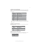
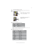
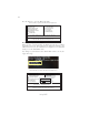
F_AUDIO: Front Panel Audio header
This header allows the user to install auxiliary front-oriented microphone and line-
out ports for easier access.
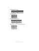
F_USB1~4: Front Panel USB headers
The motherboard has six USB ports installed on the rear edge I/O port array. Addi-
tionally, some computer cases have USB ports at the front of the case. If you have
this kind of case, use auxiliary USB connector to connect the front-mounted ports to
the motherboard.
Please make sure that the USB cable has the same pin assignment as
indicated above. A different pin assignment may cause damage or system
hang-up.
1 USBPWR Front Panel USB Power
2 USBPWR Front Panel USB Power
3 USB_FP_P0- USB Port 0 Negative Signal
4 USB_FP_P1- USB Port 1 Negative Signal
5 USB_FP_P0+ USB Port 0 Positive Signal
6 USB_FP_P1+ USB Port 1 Positive Signal
7 GND Ground
8 GND Ground
9 Key No pin
10 USB_FP_OC0 Overcurrent signal
Function
Pin Signal Name
Pin Signal Name Function
1 PORT 1L 2 AUD_GND
3 PORT 1R 4 PRESENCE#
5 PORT 2R 6 SENSE1_RETURN
7 SENSE_SEND 8 KEY
Pin Signal Name
9 PORT 2L 10 SENSE2_RETURN
Pin Signal Name
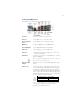
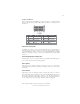
CASE: Chassis Intrusion Detect Header
Short Chassis cover is removed
Open Chassis cover is closed
Pin 1-2 Function
This detects if the chassis cover has been removed. This function needs a chassis
equipped with instrusion detection switch and needs to be enabled in BIOS.