Preface Copyright This publication, including all photographs, illustrations and software, is protected under international copyright laws, with all rights reserved. Neither this manual, nor any of the material contained herein, may be reproduced without written consent of the author. Version 1.0 Disclaimer The information in this document is subject to change without notice.
ii Declaration of Conformity This device complies with part 15 of the FCC rules. Operation is subject to the following conditions: • This device may not cause harmful interference. • This device must accept any interference received, including interference that may cause undesired operation. Canadian Department of Communications This class B digital apparatus meets all requirements of the Canadian Interferencecausing Equipment Regulations.
iii TABLE OF CONTENTS Preface i Chapter 1 1 Introducing the Motherboard 1 Introduction...................................................................................1 Feature............................................................................................2 Specifications................................................................................4 Motherboard Components..........................................................
iv Security Menu.........................................................................54 Exit Menu...............................................................................55 Updating the BIOS..................................................................57 Chapter 4 59 Using the Motherboard Software 59 About the Software DVD-ROM/CD-ROM...................................59 Auto-installing under Windows XP/Vista/7..................................59 Running Setup...............................
1 Chapter 1 Introducing the Motherboard Introduction Thank you for choosing the H61H2-M12 motherboard. This motherboard is a high performance, enhanced function motherboard designed to support the LGA1155 socket for new 2nd Generation Intel CoreTM i7/i5/i3 series processor/Intel Pentium /Celeron processors for high-end business or personal desktop markets. This motherboard is based on Intel H61 Express Chipset for best desktop platform solution.
2 Feature Processor The motherboard uses an LGA1155 type of socket that carries the following features: • Accommodates new 2nd Generation Intel CoreTM i7/i5/i3 series processor/ Intel Pentium /Celeron processors • Supports “Hyper-Threading” technology CPU • One PCI Express x16 Gen2 port supporting up to 5 GB/s direction peak bandwidth “Hyper-Threading” technology enables the operating system into thinking it’s hooked up to two processors, allowing two threads to be run in parallel, both on separate “lo
3 Onboard LAN (Optional) The onboard LAN provides the following features: • • • Supports PCI ExpressTM 1.1 Integrated 10/100/1000 transceiver Wake-on-LAN and remote wake-up support • • • Supports PCI ExpressTM 1.1 Integrated 10/100 transceiver Wake-on-LAN and remote wake-up support Expansion Options The motherboard comes with the following expansion options: • • • One PCI Express x16 slot for Graphic Interface Two PCI Express x1 slots Four SATA 3.
4 Specifications • • LGA1155 socket for new 2nd Generation Intel CoreTM i7/i5/i3 series processor/Intel Pentium/Celeron processors Supports “Hyper-Threading” technology CPU DMI 20Gb/s Chipset • Intel H61 Chipset Memory • • • Dual-channel DDR3 memory architecture 2 x 240-pin DDR3 DIMM sockets support up to 16 GB Supports 1333/1066 DDR3 SDRAM Expansion Slots • • 1 x PCI Express x16 Gen2 slot 2 x PCI Express x1 slots Storage • Supported by Intel H61 Express Chipset 4 x Serial ATA 3.
5 Motherboard Components Introducing the Motherboard
6 Table of Motherboard Components LABEL 1. CPU Socket 2. CPU_FAN 3. DDR3_1~2 4. ATX_POWER 5. SPI_DEBUG 6. SATA1~4 7. F_PANEL 8. F_USB1~2 9. CASE 10. USBPWR_F1 11. SPK 12. LDC 13. COM 14. ME_UNLOCK 15. SYS_FAN 16. F_AUDIO 17. CLR_CMOS 18. PCIE1~2 19. PCIEX16 20. USBPWR_R1 21.
7 Chapter 2 Installing the Motherboard Safety Precautions • • • • • Follow these safety precautions when installing the motherboard Wear a grounding strap attached to a grounded device to avoid damage from static electricity Discharge static electricity by touching the metal case of a safely grounded object before working on the motherboard Leave components in the static-proof bags they came in Hold all circuit boards by the edges.
8 Do not over-tighten the screws as this can stress the motherboard. Checking Jumper Settings This section explains how to set jumpers for correct configuration of the motherboard. Setting Jumpers Use the motherboard jumpers to set system configuration options. Jumpers with more than one pin are numbered. When setting the jumpers, ensure that the jumper caps are placed on the correct pins. The illustrations show a 2-pin jumper. When the jumper cap is placed on both pins, the jumper is SHORT.
9 Checking Jumper Settings The following illustration shows the location of the motherboard jumpers. Pin 1 is labeled. Jumper Settings Type Description CLR_CMOS 3-pin Clear CMOS Jumper Setting (default) 1-2: NORMAL 2-3: CLEAR Before clearing the CMOS, make sure to turn off the system. Front Panel USBPWR_F1 3-pin USB Power Select Jumper 1-2: VCC Rear USB PS/2 USBPWR_R1 3-pin Power Select Jumper 1-2: VCC 1 CLR_CMOS 1 2-3: DIMM_5VDUAL USBPWR_F1 1 2-3: DIMM_5VDUAL USBPWR_R1 1.
10 Installing Hardware Installing the Processor Caution: When installing a CPU heatsink and cooling fan make sure that you DO NOT scratch the motherboard or any of the surface-mount resistors with the clip of the cooling fan. If the clip of the cooling fan scrapes across the motherboard, you may cause serious damage to the motherboard or its components. On most motherboards, there are small surface-mount resistors near the processor socket, which may be damaged if the cooling fan is carelessly installed.
11 CPU Installation Procedure The following illustration shows CPU installation components. A. Disengaging of the Load Lever · Press the hook of lever down and pull it to the right side to release it from retention tab. B. Opening of the Load Plate · Lift the tail of the load lever. · Rotate the load plate to fully open position. C. Removing the Cap · Be careful not to touch the contact at any time. D. Inserting the Package · Grasp the package. Ensure to grasp on the edge of the substrate.
12 1. To achieve better airflow rates and heat dissipation, we suggest that you use a high quality fan with 3800 rpm at least. CPU fan and heatsink installation procedures may vary with the type of CPU fan/ heatsink supplied. The form and size of fan/heatsink may also vary. 2. DO NOT remove the CPU cap from the socket before installing a CPU. 3. Return Material Authorization (RMA) requests will be accepted only if the motherboard comes with the cap on the LGA1155 socket.
13 * For reference only Installing the Motherboard
14 Expansion Slots Installing Add-on Cards The slots on this motherboard are designed to hold expansion cards and connect them to the system bus. Expansion slots are a means of adding or enhancing the motherboard’s features and capabilities. With these efficient facilities, you can increase the motherboard’s capabilities by adding hardware that performs tasks that are not part of the basic system.
15 Follow these instructions to install an add-on card: 1 2 3 Remove a blanking plate from the system case corresponding to the slot you are going to use. Install the edge connector of the add-on card into the expansion slot. Ensure that the edge connector is correctly seated in the slot. Secure the metal bracket of the card to the system case with a screw. * For reference only 1.
16 Connecting Optional Devices Refer to the following for information on connecting the motherboard’s optional devices: F_AUDIO: Front Panel Audio header This header allows the user to install auxiliary front-oriented microphone and lineout ports for easier access.
17 SATA1~4: Serial ATA connectors These connectors are used to support the Serial ATA 3.0Gb/s device, simpler disk drive cabling and easier PC assembly. It eliminates limitations of the current Parallel ATA interface. But maintains register compatibility and software compatibility with Parallel ATA. Pin Signal Name 1 3 Ground 5 7 Pin Signal Name TX+ TX- 2 4 RXGround 6 - RX+ - Ground F_USB1~2: Front Panel USB 2.0 headers The motherboard has two USB 2.0 headers supporting four USB 2.0 ports.
18 CASE: Chassis Intrusion Detect Header This detects if the chassis cover has been removed. This function needs a chassis equipped with instrusion detection switch and needs to be enabled in BIOS. Pin 1-2 Function Short Chassis cover is removed Open Chassis cover is closed ME_UNLOCK: ME Unlock Header Pin 1-2 Function Short Unlock Open Lock COM: Onboard serial port header Connect a serial port extension bracket to this header to add a serial port to your system.
19 Installing a SATA Hard Drive This section describes how to install a SATA Hard Drive. About SATA Connectors Your motherboard features four SATA connectors supporting a total of four drives. SATA refers to Serial ATA (Advanced Technology Attachment) is the standard interface for the IDE hard drives which are currently used in most PCs. These connectors are well designed and will only fit in one orientation.
20 Connecting I/O Devices The backplane of the motherboard has the following I/O ports: PS2 Mouse Use the upper PS/2 port to connect a PS/2 pointing device. PS2 Keyboard Use the lower PS/2 port to connect a PS/2 keyboard. VGA Port Connect your monitor to the VGA port. LAN Port Connect an RJ-45 jack to the LAN port to connect your computer to the Network. USB 2.0 Ports Use the USB 2.0 ports to connect USB 2.0 devices. Audio Ports Use the three audio ports to connect audio devices.
21 Connecting Case Components After you have installed the motherboard into a case, you can begin connecting the motherboard components. Refer to the following: 1 2 3 4 5 6 Connect the CPU cooling fan cable to CPU_FAN. Connect the standard power supply connector to ATX_POWER. Connect the case switches and indicator LEDs to the F_PANEL. Connect the system cooling fan connector to SYS_FAN. Connect the auxiliary case power supply connector to ATX12V. Connect the case speaker cable to SPK.
22 Connecting 4-pin power cable The ATX12V4P power connector is used to provide power to the CPU. When installing 4-pin power cable, the latches of power cable and the ATX12V4P match perfectly. 4-pin power cable CPU_FAN: CPU cooling FAN Power Connector Pin 1 2 3 4 Signal Name GND +12V Sense PWM Function System Ground Power +12V Sensor PWM Users please note that the fan connector supports the CPU cooling fan of 1.1A ~ 2.2A (26.4W max) at +12V.
23 ATX12V: ATX 12V Power Connector Pin 1 2 3 4 Signal Name Ground Ground +12V +12V SPK: Internal speaker Pin Signal Name 1 2 3 4 VCC Key GND Signal Installing the Motherboard
24 Front Panel Header The front panel header (F_PANEL) provides a standard set of switch and LED headers commonly found on ATX or Micro ATX cases.
25 Chapter 3 Using BIOS About the Setup Utility The computer uses the latest “American Megatrends Inc. ” BIOS with support for Windows Plug and Play. The CMOS chip on the motherboard contains the ROM setup instructions for configuring the motherboard BIOS. The BIOS (Basic Input and Output System) Setup Utility displays the system’s configuration status and provides you with options to set system parameters.
26 Press the delete key to access BIOS Setup Utility. Resetting the Default CMOS Values When powering on for the first time, the POST screen may show a “CMOS Settings Wrong” message. This standard message will appear following a clear CMOS data at factory by the manufacturer. You simply need to Load Default Settings to reset the default CMOS values. Note: Changes to system hardware such as different CPU, memories, etc. may also trigger this message.
27 In this manual, default values are enclosed in parenthesis. Submenu items are denoted by a icon . The default BIOS setting for this motherboard apply for most conditions with optimum performance. We do not suggest users change the default values in the BIOS setup and take no responsibility to any damage caused by changing the BIOS settings.
28 Advanced Select the advanced icon and press or double click the left key of the mouse to display the the following screen. Main Menu This menu shows the information of BIOS and enables you to set the system language, date and time. Main Advanced Chipset M.I.
29 Advanced Menu The Advanced menu items allow you to change the settings for the CPU and other system. Main Advanced Legacy OpROM Support Launch PXE OpROM Launch Storage OpROM Chipset M.I.
30 LAN Configuration The item in the menu shows the LAN-related information that the BIOS automatically detects. Main Advanced Chipset M.I.B III Boot LAN Configuration Onboard LAN Controller Enabled Security Exit Enabled/Disabled Onboard LAN Controller lk : Select Screen mn /Click: Select Item Enter/Dbl Click : Select +/- : Change Opt.
31 PC Health Status On motherboards support hardware monitoring, this item lets you monitor the parameters for critical voltages, temperatures and fan speeds. Main Advanced Chipset M.I.B III Boot PC Health Status Security Exit Smart Fan Function Smart Fan Function CPU Fan Speed CPU Voltage AXG Voltage DIMM Voltage : : : : 1702 RPM 1.176V 1.048 V 1.520 V -=- PECI Mode -=Offset to TCC Activation Temp. : lk : Select Screen mn /Click: Select Item Enter/Dbl Click : Select +/- : Change Opt.
32 Smart Fan Mode (Normal) This item allows you to select the fan mode (Normal, Quiet, Silent, or Manual) for a better operation environment. If you choose Normal mode, the fan speed will be auto adjusted depending on the CPU temperature. If you choose Quite mode, the fan speed will be auto minimized for quiet environment. If you choose Silent mode, the fan speed will be auto restricted to make system more quietly. If you choose Manual mode, the fan speed will be adjust depending on users’ parameters.
33 Power Management Setup This page sets up some parameters for system power management operation. Main Advanced Chipset M.I.B III Boot Power Management Setup Resume By Ring Resume By PME Resume By USB2.0 (S3) Resume By PS2 KB (S3) Resume By PS2 MS (S3) EUP Function Power LED Type Security Exit About Resume by Ring Disabled Disabled Disabled Disabled Disabled Enabled Dual Color LED lk : Select Screen mn /Click: Select Item Enter/Dbl Click : Select +/- : Change Opt.
34 ACPI Configuration The item in the menu shows the highest ACPI sleep state when the system enters suspend. Aptio Setup Utility - Copyright (C) 2011 American Megatrends, Inc. Main Advanced Chipset M.I.B III Boot ACPI Settings ACPI Sleep State S3 (Suspend to RAM) Security Exit Select the highest ACPI sleep state the system will enter when the Suspend button is pressed. lk : Select Screen mn /Click: Select Item Enter/Dbl Click : Select +/- : Change Opt.
35 CPU Configuration The item in the menu shows the CPU. Main Advanced Chipset M.I.B III Boot CPU Configuration Security Exit Disabled for Windows XP Intel(R) Core(TM) i5-2400 CPU @ 3.
36 Execute Disable Bit (Enabled) This item allows the processor to classify areas in memory by where application codecan execute and where it cannot. When a malicious worm attempts to insert code inthe buffer, the processor disables code execution, preventing damage or worm propa-gation. Replacing older computers with Execute Disable Bit enabled systems can haltworm attacks, reducing the need for virus related repair.
37 Main Advanced Chipset M.I.B III Boot SATA Configuration SATA Mode Aggressive Link Power Management AHCI Mode Enabled Security Exit (1) IDE Mode. (2) AHCI Mode. SATA Port1 Staggered Spin-up External SATA Port Not Present Disabled Disabled SATA Port2 Staggered Spin-up External SATA Port Not Present Disabled Disabled lk : Select Screen mn /Click: Select Item SATA Port3 Staggered Spin-up External SATA Port Not Present Disabled Disabled +/- : Change Opt.
38 USB Configuration Use this item to show the information of USB configuration. Main Advanced Chipset M.I.B III Boot USB Configuration Security Exit Enabled/Disabled All USB Devices All USB Devices Enabled Legacy USB Support Enabled lk : Select Screen mn /Click: Select Item Enter/Dbl Click : Select +/- : Change Opt. F1: General Help F2: Previous Values F3: Optimized Defaults F4: Save & Exit ESC/Right Click: Exit All USB Devices (Enabled) Use this item to enable or disable all USB devices.
39 Super IO Configuration Use this item to show the information of Super IO configuration. Main Advanced Chipset M.I.B III Boot Super IO Configuration Super IO Chip Serial Port 0 Configuration Security Exit Set Parameters of Serial Port 0 (COMA) Finteck F71808 lk : Select Screen mn /Click: Select Item Enter/Dbl Click : Select +/- : Change Opt.
40 Chipset Menu The chipset menu items allow you to change the settings for the North Bridge chipset, South Bridge chipset and other system. Main Advanced Chipset M.I.B III Boot North Bridge South Bridge Me Subsystem Security Exit North Bridge Parameters lk : Select Screen mn /Click: Select Item Enter/Dbl Click : Select +/- : Change Opt.
41 IGD Multi-Monitor (Enabled) This item enables or disables IGD(Internal Graphics device) multi-monitor. Press to return to the Chipset Menu page. Multi-Monitor technology Multi-Monitor technology can help you to increase the area available for programs running on a single computer system through using multiple display devices. It is not only to increase larger screen viewing but aslo to improving personal productivity.
42 Step 2. Install all the drivers of PCI-Express graphic cards. Click the Browse CD item, then appears the following screen. Select the driver you want to install(e.g NVIDIA GeForce 8400 GS(Microsoft Corporation-WDDM v1.1)) and double click it. Step 3. Enable IGD Multi-Monitor from BIOS. In the following BIOS screen, please set IGD Multi-Monitor to [Enabled]. Main Advanced Chipset M.I.
43 Step 4. Change the appearance of your displays under Windows 7. 1. Enter the Control Panel menu, select the Display in the All Control Panel Items and click the Screen Resolution, then appears the following screen. Show the path of the setting location Display devices Control Panel All Control Panel Items Display Screen Resolution Search Control Panel Change the apprearance of your displays 2 Detect 3 1 Display: 1.
44 Control Panel All Control Panel Items Display Screen Resolution Search Control Panel Change the apprearance of your displays Detect 3 2 Identify 1 Display: 3. AL1717 Resolution: 1920 x 1200 (recommended) Orientation: Landscape Multiple displays: Disconnect this display ! You must select Apply before making additional changes.
45 fSouth Bridge Scroll to this item and press to view the following screen. Main Advanced Chipset M.I.B III Boot South Bridge Restore AC Power Loss Power Off Audio Configuration Azalia HD Audio Enabled Case Open Warning Chassis Opened Disabled No Security Exit Specify what state to go to when power is re-applied after a power failure (G3 state). lk : Select Screen mn /Click: Select Item Enter/Dbl Click : Select +/- : Change Opt.
46 f ME Subsystem Scroll to this item and press to view the following screen. Main Advanced Chipset M.I.B III Boot Intel ME Subsystem Configuration ME Version Security Exit ME Subsystem Help 7.0.4.1197 ME Subsystem Enabled lk : Select Screen mn /Click: Select Item Enter/Dbl Click : Select +/- : Change Opt. F1: General Help F2: Previous Values F3: Optimized Defaults F4: Save & Exit ESC/Right Click: Exit ME Version (7.0.4.1197) This item shows the ME version.
47 M.I.B III (MB Intelligent BIOS III) Menu This page enables you to set the clock speed and system bus for your system. The clock speed and system bus are determined by the kind of processor you have installed in your system. Main Advanced Chipset M.I.B III Boot M.I.B III (MB Intelligent BIOS III) Security Exit Integrated Clock Chip Parameters Integrated Clock Chip Configuration Memory Voltage Control Performance Tuning B.O.M.P.
48 ICC Enable (Disabled) This item allows you to enable or disable current ICC. Press to return to the M.I.B III Menu page. f Memory Voltage Control Scroll to this item to view the following screen: Main Advanced Chipset M.I.B III Boot Memory Voltage Control Security Exit Memory Voltage Control Memory Voltage Config Auto lk : Select Screen mn /Click: Select Item Enter/Dbl Click : Select +/- : Change Opt.
49 f Performance Tunning Scroll to this item to view the following screen: Main Advanced Chipset M.I.B III Boot Performance Tunning Security Exit CPU Configuration CPU Configuration Chipset Configuration lk : Select Screen mn /Click: Select Item Enter/Dbl Click : Select +/- : Change Opt. F1: General Help F2: Previous Values F3: Optimized Defaults F4: Save & Exit ESC/Right Click: Exit fCPU Configuration Scroll to this item to view the following screen: Main Advanced Chipset M.I.
50 Enhanced Intel SpeedStep Technology (Enabled) This item allows users to enable or disable the EIST (Enhanced Intel SpeedStep Technology). Long Duration Maintained (1) Use this item to control the time window over PL1 value should be maintained. This is for Turbo mode. Turbo Mode (Enabled) This item allows you to control the Intel Turbo Boost Technology. 1/2/3/4 Core Ratio (34/33/33/32) This item shows the Core Ratio limit value. Press to return to the Performance Tunning page.
51 f Chipset Configuration Scroll to this item to view the following screen: Main Advanced Chipset M.I.B III Boot Memory Multiplier Configuration Memory Multiplier 13.
52 Active to Active Delay(tRRD) (4) This item controls the ACTIVE bank x to ACTIVE bank y delay in memory clock cycles. Read CAS# Precharge (tRTP) (5) This item controls the Read to PRECHARGE delay for memory devices, in memory clock cycles. Four Active Window Delay(tFAW) (20) This item controls the four bank activate time in memory clock cycles. GT OverClocking (Disabled) This item allows you to control the internal GFX Turbo mode. Press to return to the Performance Tunning page.
53 Boot Menu This page enables you to set the keyboard NumLock state. Main Advanced Chipset M.I.
54 NETWORK Device BBS Priorities This item enables you to specify the sequence of loading the operating system from the installing network devices. UEFI Boot Drive BBS Priorities This item enables you to specify the sequence of loading the operating system from the installing UEFI Boot drives. Security Menu This page enables you to set setup administrator password and user password. Main Advanced Chipset M.I.
55 Exit Menu This page enables you to exit system setup after saving or without saving the changes. Main Advanced Chipset M.I.B III Boot Back to EZ Mode Security Exit Go back to EZ Mode Save Changes and Exit Discard Changes and Exit Save Changes and Reset Discard Changes and Reset lk : Select Screen mn /Click: Select Item Enter/Dbl Click : Select +/- : Change Opt.
56 Boot Override Use this item to select the boot device.
57 Updating the BIOS You can download and install updated BIOS for this motherboard from the manufacturer’s Website. New BIOS provides support for new peripherals, improvements in performance, or fixes for known bugs. Install new BIOS as follows: 1 If your motherboard has a BIOS protection jumper, change the setting to allow BIOS flashing. 2 If your motherboard has an item called Firmware Write Protect in Advanced BIOS features, disable it. (Firmware Write Protect prevents BIOS from being overwritten.
58 Memo Using BIOS
59 Chapter 4 Using the Motherboard Software About the Software DVD-ROM/CD-ROM The support software DVD-ROM/CD-ROM that is included in the motherboard package contains all the drivers and utility programs needed to properly run the bundled products. Below you can find a brief description of each software program, and the location for your motherboard version. More information on some programs is available in a README file, located in the same directory as the software.
60 Drivers Setup Click the Setup button to run the software installation program. Select from the menu which software you want to install. Utilities Click the Utilities button to display the application software and other software utilities that are available on the disk. Select the sofware you want to install then follow installation procedure. Browse CD The Browse CD button is the standard Windows command that allows you to open Windows Explorer and show the contents of the support disk.
61 2. Click Next. The following screen appears: 3. Check the box next to the items you want to install. The default options are recommended. 4. Click Next run the Installation Wizard. An item installation screen appears: 5. Follow the instructions on the screen to install the items. Drivers and software are automatically installed in sequence. Follow the onscreen instructions, confirm commands and allow the computer to restart a few times to complete the installation.
62 Windows Vista/7 will appear below UAC (User Account Control) message after the system restart. You must select “Allow” to install the next driver. Continue this process to complete the drivers installation. Manual Installation Insert the disk in the DVD-ROM/CD-ROM drive and locate the PATH.DOC file in the root directory. This file contains the information needed to locate the drivers for your motherboard.
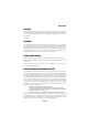
63 Chapter 5 Trouble Shooting Start up problems during assembly After assembling the PC for the first time you may experience some start up problems. Before calling for technical support or returning for warranty, this chapter may help to address some of the common questions using some basic troubleshooting tips. a) System does not power up and the fans are not running. 1.Disassemble the PC to remove the VGA adaptor card, DDR memory, LAN, USB and other peripherals including keyboard and mouse.
64 2. From the BIOS setting, try to disable the Smartfan function to let the fan run at default speed. Doing a Load Optimised Default will also disable the Smartfan. Start up problems after prolong use After a prolong period of use your PC may experience start up problems again. This may be caused by breakdown of devices connected to the motherboard such as HDD, CPU fan, etc. The following tips may help to revive the PC or identify the cause of failure. 1. Clear the CMOS values using the CLR_CMOS jumper.
If fail, contact RMA CLR CMOS and restart. Yes Halt at POST screen? Yes Check if monitor has display Yes Check if Power Supply Unit (PSU) is working Power Bu on is pressed but PC fails to start. CMOS setup error, - need to CLRCMOS. HDD problem.
66 Memo Trouble Shooting