Preface Copyright This publication, including all photographs, illustrations and software, is protected under international copyright laws, with all rights reserved. Neither this manual, nor any of the material contained herein, may be reproduced without written consent of the author. Version 1.0 Disclaimer The information in this document is subject to change without notice.
ii Declaration of Conformity This device complies with part 15 of the FCC rules. Operation is subject to the following conditions: • • This device may not cause harmful interference, and This device must accept any interference received, including interference that may cause undesired operation Canadian Department of Communications This class B digital apparatus meets all requirements of the Canadian Interferencecausing Equipment Regulations.
iii TABLE OF CONTENTS Preface i Chapter 1 1 Introducing the Motherboard 1 Introduction......................................................................................1 Feature...............................................................................................2 Motherboard Components.............................................................4 Chapter 2 7 Installing the Motherboard 7 Safety Precautions...........................................................................
iv Frequency/Voltage Control.................................................35 Load Default Settings.........................................................36 Supervisor Password.........................................................36 User Password...................................................................37 Save & Exit Setup...............................................................37 Exit Without Saving.............................................................37 Updating the BIOS.....
1 Chapter 1 Introducing the Motherboard Introduction Thank you for choosing TIGT-I2 motherboard of great performance and with enhanced function. This motherboard has onboard Intel® AtomTM D410 CPU with an ITX form factor of 170 x 170 mm. This motherboard is based on Intel® NM10 Chipset for best desktop platform solution. NM10 is a single-chip, highly integrated, high performance Hyper-Threading peripheral controller, unmatched by any other single chip-device controller.
2 Feature Processor This motherboard uses onboard Intel® AtomTM D410 CPU that carries the following features: • • Onboard Intel® AtomTM D410 CPU Supports “Hyper-Threading” technology CPU “Hyper-Threading” technology enables the operating system into thinking it’s hooked up to two processors, allowing two threads to be run in parallel, both on separate “logical” processors within the same physical processor. Chipset The Intel NM10 Chipset is a single-chip with proven reliability and performance.
3 Expansion Options The motherboard comes with the following expansion options: • • One PCI Express x1 slots Two 7-pin SATA connectors Integrated I/O The motherboard has a full set of I/O ports and connectors: • • • • • • • Two PS/2 ports for mouse and keyboard One LPT port One serial port One VGA port Four USB ports One LAN port Audio jacks for microphone, line-in and line-out BIOS Firmware This motherboard uses AMI BIOS that enables users to configure many system features including the following: • •
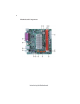
4 Motherboard Components Introducing the Motherboard
5 Table of Motherboard Components LABEL 1. LVDS* 2. CPU_FAN 3. DDR2_1~2 4. SYS_FAN 5. ATX_POWER 6. F_PANEL 7. CLR_CMOS 8. SPK 9. SATA1~2 10. F_USB1~2 11. USBPWR_F 12. PCIE 13. F_AUDIO 14. SPDIFO 15. USBPWR_R 16.
6 Memo Introducing the Motherboard
7 Chapter 2 Installing the Motherboard Safety Precautions • • • • • Follow these safety precautions when installing the motherboard Wear a grounding strap attached to a grounded device to avoid damage from static electricity Discharge static electricity by touching the metal case of a safely grounded object before working on the motherboard Leave components in the static-proof bags they came in Hold all circuit boards by the edges.
8 Do not over-tighten the screws as this can stress the motherboard. Checking Jumper Settings This section explains how to set jumpers for correct configuration of the motherboard. Setting Jumpers Use the motherboard jumpers to set system configuration options. Jumpers with more than one pin are numbered. When setting the jumpers, ensure that the jumper caps are placed on the correct pins. The illustrations show a 2-pin jumper. When the jumper cap is placed on both pins, the jumper is SHORT.
9 Checking Jumper Settings The following illustration shows the location of the motherboard jumpers. Pin 1 is labeled. Jumper Settings Jumper Type Description Setting (default) CLR_CMOS 3-pin CLEAR CMOS 1-2: NORMAL 2-3: CLEAR 1 Before clearing the CMOS, make sure to turn the system off. CLR_CMOS Rear USB/PS2 USBPWR_F 3-pin Power Select Jumper 1-2: VCC5 2-3: VCC5_DUAL 1 USBPWR_F Front Panel USBPWR_R 3-pin USB Power Select Jumper 1 1-2: VCC5 2-3: VCC5_DUAL USBPWR_R 1.
10 Installing Hardware Installing Memory Modules This motherboard accommodates two memory module. It can support two 240-pin DDR2 800/667. The total memory capacity is 4 GB. DDR2 SDRAM memory module table Memory module Memory Bus DDR2 667 333 MHz DDR2 800 400 MHz Do not remove any memory module from its antistatic packaging until you are ready to install it on the motherboard. Handle the modules only by their edges. Do not touch the components or metal parts.
11 Table A: DDR2 (memory module) QVL (Qualified Vendor List) The following DDR2 800/667 memory modules have been tested and qualified for use with this motherboard. Type Size Vendor Module Nam e 512 MB Micron MT4HTF6464AY-667E1 AU01GE667C5KBGC Apacer 78.01G9O.9K5 Corsair 1GB VS1GB667D2 Kingston KVR667D2N5 Micron MT8HTF12864AY-667E1 AL7E8E63B-6E1T PSC DDR 667 AL7E8F63J-6E1 AL7E8F73C-6E1 Samsung 2GB Golden Bar M378T2863DZS 0742 Apacer 78.A1G9O.
12 Type Size Vendor Module Nam e A-DATA M2GVD6G3I41P0U1E5E AU01GE800C5KBGC Apacer 78.01G9O.9K5 78.01GA0.9L5 Geil Geil Millenary Hynix HYMP112U64CP8-S6 AB KingMax KLDD48F-B8KU5 NGES Kingston KVR800D2N5/1G 1.8V 9905316-054.A01LF Nanya NT1GT64U88D0BY-AD 1GB Ramaxel RML1320EH38D7F-800 Golden Bar M378T2953EZ3-CE7 0726 Samsung M378T2863EHS-CF7 0849 Transcend DIMM 5-5-5 Unifosa GU341G0ALEPR6B2C6CE A-DATA Red A-DATA M2OMI6H3J4720L1C5Z DDR2 800 78.A1GAO.9K4 Apacer 78.A1GC0.
13 Expansion Slots Installing Add-on Cards The slots on this motherboard are designed to hold expansion cards and connect them to the system bus. Expansion slots are a means of adding or enhancing the motherboard’s features and capabilities. With these efficient facilities, you can increase the motherboard’s capabilities by adding hardware that performs tasks that are not part of the basic system. PCIE Slot The PCI Express x1 slots is fully compliant to the PCI Express Gen 1 (version 1.0a).
14 Connecting Optional Devices Refer to the following for information on connecting the motherboard’s optional devices: F_AUDIO: Front Panel Audio header This header allows the user to install auxiliary front-oriented microphone and lineout ports for easier access.
15 CASE: Chassis Intrusion Detect Header Pin 1-2 Function Short Case Open Open Case Close F_USB1~2: Front Panel USB headers The motherboard has four USB ports installed on the rear edge I/O port array. Additionally, some computer cases have USB ports at the front of the case. If you have this kind of case, use auxiliary USB connector to connect the front-mounted ports to the motherboard.
16 LVDS: LVDS connector (optional) Pin 1 3 5 Signal Name Pin Signal Name 7 9 11 13 GND PWM_LED 15 17 V_EDID RXIN0- 2 4 6 8 10 12 14 16 18 19 GND 20 21 RXIN1+ 22 GND 23 RXIN2- 24 RXIN2+ 25 GND 26 RXCLK+ 27 RXCLK- 28 GND 29 DATA-EDID 30 CLK-EDID VDD GND V_LED USB_VCC USB_D+ VDD USB_GND V_LED GND EN_LED USB_DUSB_GND GND RXIN0+ RXIN1- Installing a Hard Disk Drive/CD-ROM/SATA Hard Drive This section describes how to install IDE devices such as a hard disk drive and a CDROM dr
17 Refer to 1 2 3 the illustration below for proper installation: Attach either cable end to the connector on the motherboard. Attach the other cable end to the SATA hard drive. Attach the SATA power cable to the SATA hard drive and connect the other end to the power supply. This motherboard supports the “Hot-Plug” function. Connecting I/O Devices The backplane of the motherboard has the following I/O ports: PS2 Mouse Use the upper PS/2 port to connect a PS/2 pointing device.
18 Connecting Case Components After you have installed the motherboard into a case, you can begin connecting the motherboard components. Refer to the following: 2 3 4 Connect the case switches and indicator LEDs to the F_PANEL. Connect the standard power supply connector to ATX_POWER. Connect the case speaker cable to SPK. Connecting 24-pin power cable The ATX 24-pin connector allows you to connect to ATX v2.x power supply. With ATX v2.
19 CPU_FAN: FAN Power Connectors Pin 1 2 3 4 Signal Name GND +12V Sense Control Function System Ground Power +12V Sensor CPU FAN control 1.Users please note that the fan connector supports the CPU cooling fan of 1.1A ~ 2.2A (26.4W max) at +12V. 2.Users please note that this connector can be used as CASE_FAN for quiet operation. ATX_POWER: ATX 24-pin Power Connector Pin Signal Name 1 2 3 4 5 6 7 8 9 +3.3V 10 11 12 +12V Pin 13 14 15 16 17 18 19 20 21 +3.
20 Front Panel Header The front panel header (F_PANEL) provides a standard set of switch and LED headers commonly found on ATX or Micro ATX cases.
21 Chapter 3 Using BIOS About the Setup Utility The computer uses the latest “American Megatrends Inc. ” BIOS with support for Windows Plug and Play. The CMOS chip on the motherboard contains the ROM setup instructions for configuring the motherboard BIOS. The BIOS (Basic Input and Output System) Setup Utility displays the system’s configuration status and provides you with options to set system parameters.
22 Press the delete key to access the BIOS Setup Utility. CMOS Setup Utility - Copyright (C) 1985-2005, American Megatrends, Inc. Standard CMOS Setup Advanced Setup Advanced Chipset Setup Integrated Peripherals Power Management Setup PC Health Status Frequency/Voltage Control Load Default Settings Supervisor Password User Password Save & Exit Setup Exit Without Saving : Move Enter : Select F1:General Help +/-/: Value F10: Save ESC: Exit F9: Optimized Defaults v02.
23 Using BIOS When you start the Setup Utility, the main menu appears. The main menu of the Setup Utility displays a list of the options that are available. A highlight indicates which option is currently selected. Use the cursor arrow keys to move the highlight to other options. When an option is highlighted, execute the option by pressing . Some options lead to pop-up dialog boxes that prompt you to verify that you wish to execute that option.
24 For the purpose of better product maintenance, we reserve the right to change the BIOS items presented in the manual. The BIOS setup screens shown in this chapter are for reference only. Please visit our website for updated manual. Standard CMOS Setup This option displays basic information about your system. CMOS Setup Utility - Copyright (C) 1985-2005, American Megatrends, Inc.
25 Type (Auto) Use this item to configure the type of the IDE device that you specify. If the feature is enabled, it will enhance hard disk performance by reading or writing more data during each transfer. LBA/Large Mode (Auto) Use this item to set the PIO mode to enhance hard disk performance by optimizing the hard disk timing. Block (Multi-Sector Transfer) (Auto) If the feature is enabled, it will enhance hard disk performance by reading or writingmore data during each transfer.
26 Advanced Setup This page sets up more advanced information about your system. Handle this page with caution. Any changes can affect the operation of your computer. CMOS Setup Utility - Copyright (C) 1985-2005, American Megatrends, Inc.
27 1st/2nd/3rd Boot Device (Hard Disk Drive/CD/DVD/Removable Dev.) Use this item to determine the device order the computer used to look for an operating system to load at start-up time. The devices showed here will be different depending on the exact devices installed on your motherboard. Hard Disk Drives (Press Enter) Scroll to this item and press to view the following screen: CMOS Setup Utility - Copyright (C) 1985-2005, American Megatrends, Inc.
28 Advanced Chipset Setup This page sets up more advanced information about your system. Handle this page with caution. Any changes can affect the operation of your computer. CMOS Setup Utility - Copyright (C) 1985-2005, American Megatrends, Inc.
29 Integrated Peripherals This page sets up some parameters for peripheral devices connected to the system. CMOS Setup Utility - Copyright (C) 1985-2005, American Megatrends, Inc.
30 Parallel Port IRQ (IRQ7) Use this item to assign IRQ to the parallel port. USB Functions (Enabled) Use this item to enable or disable the USB function. Legacy USB Support (Enabled) Use this item to enable or disable support for legacy USB devices. Press to return to the main menu setting page. Power Management Setup This page sets up some parameters for system power management operation. CMOS Setup Utility - Copyright (C) 1985-2005, American Megatrends, Inc.
31 Resume By USB (S3) (Disabled) This item allows you to enable/disable the USB device wakeup function from S3/S4 mode. Resume By PS2 KB (S3) (Disabled) This item enables or disables you to allow keyboard activity to awaken the system from power saving mode. Resume By PS2 MS (S3) (Disabled) This item enables or disables you to allow mouse activity to awaken the system from power saving mode. Resume on RTC Alarm (Disabled) The system can be turned off with a software command.
32 PC Health Status On motherboards support hardware monitoring, this item lets you monitor the parameters for critical voltages, temperatures and fan speeds. CMOS Setup Utility - Copyright (C) 1985-2005, American Megatrends, Inc. PC Health Status Help Item -=- System Hardware Monitor -=Smart Fan Function Press Enter Shutdown Temperature Disabled Warning Temperature Disabled CPU Temperature : 36°C/96°F CPU FAN Speed : N/A SYS FAN Speed : N/A CPU Vcore : 1.168 V VDIMM : 1.
33 CMOS Setup Utility - Copyright (C) 1985-2005, American Megatrends, Inc. Smart Fan Function Help Item SMART Fan Control SMART Fan Mode SMART Fan start PWM value DeltaT SMART Fan start TEMP.(° C) SMART Fan Slope PWM value CPU FAN Full Limit Temp Enabled Normal 28 +3 43 5 PWM value/° C 63° C : Move Enter : Select F1: General Help Options Disabled Enabled +/-/: Value F10: Save ESC: Exit F9: Optimized Defaults CMOS Setup Utility - Copyright (C) 1985-2005, American Megatrends, Inc.
34 CMOS Setup Utility - Copyright (C) 1985-2005, American Megatrends, Inc. Smart Fan Function SMART Fan Control SMART Fan Mode SMART Fan start PWM value DeltaT SMART Fan start TEMP.(° C) SMART Fan Slope PWM value CPU FAN Full Limit Temp Enabled Silent 5 +3 70 12 PWM value/° C 80° C Help Item Options Normal: auto adjusts depending on the CPU temperature. Quiet: auto minimizes fan speed for quiet environment operation. Silent: auto restricts fan speed to make system more quietly.
35 System Component Characteristics These items display the monitoring of the overall inboard hardware health events, such as System & CPU temperature, CPU & DIMM voltage, CPU & system fan speed,...etc. • • • • CPU Fan Speed CPU Vcore VDIMM VBAT Case Open Warning (Disabled) This item enables or disables the warning if the case is opened up, and the item below indicates the current status of the case. Chassis Opened (No) This item indicates whether the case has been opened.
36 Load Default Settings This option opens a dialog box that lets you install stability-oriented defaults for all appropriate items in the Setup Utility. Select and then press to install the defaults. Select and then press to not install the defaults. Supervisor Password This page helps you install or change a password. CMOS Setup Utility - Copyright (C) 1985-2005, American Megatrends, Inc.
37 User Password This page helps you install or change a password. CMOS Setup Utility - Copyright (C) 1985-2005, American Megatrends, Inc. User Password User Password : Not Installed : Move Enter : Select F1: General Help Help Item +/-/: Value F10: Save ESC: Exit F9: Load Default Settings User Password (Not Installed) This item indicates whether a user password has been set. If the password has been installed, Installed displays. If not, Not Installed displays.
38 Updating the BIOS You can download and install updated BIOS for this motherboard from the manufacturer’s Web site. New BIOS provides support for new peripherals, improvements in performance, or fixes for known bugs. Install new BIOS as follows: 1 If your motherboard has a BIOS protection jumper, change the setting to allow BIOS flashing. 2 If your motherboard has an item called Firmware Write Protect in Advanced BIOS features, disable it. (Firmware Write Protect prevents BIOS from being overwritten.
39 Chapter 4 Using the Motherboard Software About the Software DVD-ROM/CD-ROM The support software DVD-ROM/CD-ROM that is included in the motherboard package contains all the drivers and utility programs needed to properly run the bundled products. Below you can find a brief description of each software program, and the location for your motherboard version. More information on some programs is available in a README file, located in the same directory as the software.
40 Drivers Tab Setup Click the Setup button to run the software installation program. Select from the menu which software you want to install. Browse CD The Browse CD button is the standard Windows command that allows you to open Windows Explorer and show the contents of the support disk. Before installing the software from Windows Explorer, look for a file named README.TXT or something similar. This file may contain important information to help you install the software correctly.
41 2. Click Next. The following screen appears: 3. Check the box next to the items you want to install. The default options are recommended. 4. Click Next run the Installation Wizard. An item installation screen appears: 5. Follow the instructions on the screen to install the items. 1. Drivers and software are automatically installed in sequence. Follow the onscreen instructions, confirm commands and allow the computer to restart a few times to complete the installation. 2.
42 Windows Vista/7 will appear below UAC (User Account Control) message after the system restart. You must select “Allow” to install the next driver. Continue this process to complete the drivers installation. Manual Installation Insert the disk in the DVD-ROM/CD-ROM drive and locate the PATH.DOC file in the root directory. This file contains the information needed to locate the drivers for your motherboard.
43 Chapter 5 Setting Up eJIFFY Introduction eJIFFY is a fast boot program under Linux. Instead of waiting Windows O.S to start execution, eJIFFY is ready to provide users the instant enjoyment on web browsing, photo review and online chat just within several seconds after boot up. Note: eJIFFY is ECS optional feature utility corresponding to the DVD activation and BIOS setup. Please check the hard copy user’s guide or product color-box to see if the model has embodded eJIFFY feature.
44 Installation and BIOS Setup DVD Activation Finish the DVD utility setup, and then set the BIOS to complete eJIFFY activation. 1. Insert ECS software utility DVD and enter below “Utilities” screen. Click eJIFFY feature item to install. 2. Follow the onscreen instructions to finish eJIFFY setup.
45 3. After setting up eJIFFY under Windows, you can switch eJIFFY display/keyboard language from English to your local language. The changes will be applied after rebooting. Note: The keyboard language selection list offers several more regional keyboard setups to switch with the default English typing. Please refer to the usage FAQ for more tips.
46 4. Restart your computer after eJIFFY installation. Press or click the BIOS Setup button on the post screen to enter the BIOS setup page after boot up. 5. And then enter the Advanced Setup page to enable the item ECS eJIFFY Function. Press F10 to save the configuration and exit. Restart your computer. Note: 1. eJIFFY is available in SATA/IDE/AHCI mode. It does not support RAID configuration and the onboard 34-pin floppy drives. 2. Please refer to ECS website for new eJIFFY application updates.
47 Entering eJIFFY The post screen appears within several seconds after boot up and it has three buttons on it, Operating system, eJIFFY and BIOS Setup. Click to enter the normal OS you have installed such as Windows. Click to enter eJIFFY OS. Click to set the BIOS. If you click eJIFFY, the following screen will appear. And If you make no choice it will enter the normal OS automatically after ten seconds.
48 Feature Icons The following illustration shows the main feature icons that eJIFFY provides on the menu. eWeb: Firefox for web browsing/webmail and watching flash video. ePix: Photo viewing. ePal: On-line chat tool to use the most popular IMs in the world. (MSN, ICQ , AIM, etc.) Shows ePal on-line connection status. Shut Down/Restart: Ends your session and turns off the computer./Ends your session and restart the computer.. Click once to connect the storage disk to your computer.
49 Usage FAQ Language Control Panel: Besides setting English as the default interface, eJIFFY offers multi-language displays and keyboard settings for languageswitch. Open the language control panel to select a preferable language setting. Keyboard Language Setup Step1. Click to open the language control panel.
50 Step 2: Click “Keyboard Language” icon to open the keyboard selection list, which offers several regional keyboard settings besides default English keyboard. Step 3: Click the selected keyboard language (e.g. French) and press “OK”.
51 Tips for Language Switch: Tip 1: Click “Change Keyboard” icon to switch the typing language. The typing language on text box will switch to the selected one: Click again to switch to English typing back. Tip 2. If you use the default English keyboard, eJIFFY still offers other language inputs to switch with English.
52 Setting Up eJIFFY
53 Setting Up eJIFFY
54 Tip 3. How to change display language? Open the Language Control Panel and click to show the display language list. Check your desired display language. Your selected display language will be applied after rebooting.
55 eWeb: Firefox for web browsing/webmail and watching flash video. Q1: How to download files to hard disk through eWeb? Click on the file link directly. Then select “Save File” in the pop-up window. Note: 1. Before downloading files, please “mount” the storage devices to make sure the device is connected with eJIFFY interface. (Please refer to the usage FAQ to mount devices) 2. eWeb does not support Office Viewer/Reader/Writer format under eJIFFY interface.
56 Q2: How to save image file through eWeb? 1. Select the image you want to save and press the right key of your mouse to show the menu, then click the option “ Save Image As” from the menu. 2. Then the “Save Image” window appears. You may rename the image file in the “Name” column and save the file in a folder as the following picture shows. Rename the image file. Then select a subdirectory or click “Create Folder” to create a new folder. Select a root directory. Click here to save the image file.
57 ePix: Photo viewing. Q1: How to find image files saved in hard disk through ePix? Enter the ePix window, then click the icon “Folder” located in the upper left-hand corner, then follow the path for the files you have saved to view the image files.
58 Q2: How to use the fit function under slide show? 1. Click “Edit” and select “Preferences” option from the menu. 2. Click “Viewer” and choose “Keep previous zoom” in “After loading an image”. Close the window and you can use the fit function under slide show now. Note: ePix supports to view image files only. It cannot support Office Viewer or other forms beside image files. Supported image types are: BMP, JPEG, GIF (including GIF animations), PNG, TIFF, ICO and XPM.
59 Mount/Unmount Disk. Q1: What does it mean for “Mount Disk”? “ Mount” means to connect the storage devices to eJIFFY interface. After plugging the external device to the computer such as USB drives, a new disk icon will appear as the following picture shows. Please click the “mount” prompt on the icon. It will change to to show the device is detected successfully. Q2: What does it mean for “Unmount Disk”? “Unmount” is to safely remove the storage devices.
60 Memo Setting Up eJIFFY
61 Chapter 6 Trouble Shooting Start up problems during assembly After assembling the PC for the first time you may experience some start up problems. Before calling for technical support or returning for warranty, this chapter may help to address some of the common questions using some basic troubleshooting tips. a) System does not power up and the fans are not running. 1.Disassemble the PC to remove the VGA adaptor card, DDR memory, LAN, USB and other peripherals including keyboard and mouse.
62 c) The PC suddenly shuts down while booting up. 1. The CPU may experience overheating so it will shutdown to protect itself. Ensure the CPU fan is working properly. 2. From the BIOS setting, try to disable the Smartfan function to let the fan run at default speed. Doing a Load Optimised Default will also disable the Smartfan. Start up problems after prolong use After a prolong period of use your PC may experience start up problems again.
If fail, contact RMA CLR CMOS and restart. Yes Halt at POST screen? Yes Check if monitor has display Yes Check if Power Supply Unit (PSU) is working Power Bu on is pressed but PC fails to start. CMOS setup error, - need to CLRCMOS. HDD problem.
64 Memo Trouble Shooting