® 1.9 4WD ELECTRIC SCALE CRAWLER BUILD-TO-DRIVE™ KIT ECX01011 INSTRUCTION MANUAL BEDIENUNGSANLEITUNG MANUEL D’UTILISATION MANUALE DI ISTRUZIONI Congratulations on your purchase of the ECX® Barrage® 1.9 4WD Electric Scaler. This model introduces you to the sport of RC driving. Herzlichen Glückwunsch zum kauf des ECX Barrage 1.9 4WD Electric Scaler. Dieses Modell ist der gelungende Einstieg in die Welt des RC Cars Sports. Nous vous félicitons pour l’achat de l’ECX Barrage 1,9 4WD électrique.
EN NOTICE All instructions, warranties and other collateral documents are subject to change at the sole discretion of Horizon Hobby, LLC. For up-to-date product literature, visit http://www.horizonhobby.com and click on the support tab for this product.
EN WATER-RESISTANT VEHICLE WITH WATERPROOF ELECTRONICS Your new Horizon Hobby vehicle has been designed and built with a combination of waterproof and water-resistant components to allow you to operate the product in many “wet conditions,” including puddles, creeks, wet grass, snow and even rain. While the entire vehicle is highly water-resistant, it is not completely waterproof and your vehicle should NOT be treated like a submarine.
EN GETTING STARTED 1 Charge the battery 2 Assemble the chassis 3 Paint the body 4 Install the battery 5 Setup the transmitter 6 Drive! 4 2 1 5 3 CHARGING WARNINGS WARNING: Failure to exercise caution while using this product and comply with the following warnings could result in product malfunction, electrical issues, excessive heat, FIRE, and ultimately injury and property damage. • NEVER LEAVE CHARGING BATTERIES UNATTENDED. • NEVER CHARGE BATTERIES OVERNIGHT.
a1 x1 x4 x2 x1 x1 2 1 4 5 3 M2 x 8mm 1.
a2 x4 x4 x2 x1 x2 x2 NOTICE: The spindles have positive castor (see image, right). HINWEIS: Die Spindeln haben positiven Nachlauf (siehe Bild rechts). REMARQUER : Les fusées possèdent une chasse positive (voir l’image de droite). AVVISO: i fuselli hanno incidenza positiva (v. figura a destra).
b1 x1 x4 x1 x2 x1 4 5 2 1 M2 x 8mm 3 1.
b2 x4 x4 x2 x1 x2 x2 4 M2 x 6mm 2 5 4 x 8 x 3mm 1 4 x 8 x 3mm 3 M2 x 6mm 6 7 8
c1 x1 x3 x1 x1 x1 x1 x1 2 M2 x 14mm 1 3 M2 x 8mm M2 x 20mm 1.
c2 x1 x4 1 2 M3 x 8mm 10 x1
d1 x4 x4 x4 x4 x4 NOTICE: Spacer is optional. HINWEIS: Das Distanzstück ist optional. REMARQUER : L’utilisation d’une entretoise est optionnelle. AVVISO: il distanziale è opzionale. 1 4 2 3 1.
e1 x2 x1 x1 1 2 M2.5 x 5mm Tip: Leave the screws slightly loose in order to adjust the gear mesh. Tipp: Schrauben leicht gelöst belassen, um die Verzahnung anzupassen. Conseil : laissez les vis légèrement desserrées afin d’ajuster le maillage de rouages. Consiglio: lasciare le viti leggermente allentate per regolare gli ingranaggi.
e2 x2 x1 x1 x1 x1 2 M3 x 3mm 5 M2 x 4mm 1 4 3 See: SETTING THE GEAR MESH, page 30. Siehe: EINSTELLEN DES ZAHNEINGRIFFS, Seite 30. Voir la section: MONTAGE DE L’ENGRÈNEMENT DE LA ROUE DENTÉE, page 30. V.: IMPOSTAZIONE DEL RAPPORTO DEGLI INGRANAGGI, pagina 30. 1.
e3 x1 x2 x2 3 1 4 M4 x 4mm 2 M4 x 4mm 14
f1 x2 x2 x1 x1 1 3 M2 x 15mm 2 M2 x 12mm 1.
f1 x5 4 x1 x4 1 2 M3 x 10mm M3 x 10mm 3 M3 x 6mm 16 x2 x1 M3 x 6mm
g1 x2 x2 x1 x2 x2 Tip: Hold the shock and link in place while pushing the screw through the mount, shock, and link. Do not over tighten. There should be space and minimal movement between the shock and the link. Tipp: Halten Sie den Dämpfer und die Verbindungsstange in Position, während Sie die Schraube durch den Befestigungspunkt, den Dämpfer und die Verbindungsstange schieben. Nicht zu fest anziehen. Zwischen Dämpfer und Verbindungsstange sollte ein geringes Spiel bestehen.
g2 x2 x2 x1 x2 x2 Tip: Hold the shock and link in place while pushing the screw through the mount, shock, and link. Do not over tighten. There should be space and minimal movement between the shock and the link. Tipp: Halten Sie den Dämpfer und die Verbindungsstange in Position, während Sie die Schraube durch den Befestigungspunkt, den Dämpfer und die Verbindungsstange schieben. Nicht zu fest anziehen. Zwischen Dämpfer und Verbindungsstange sollte ein geringes Spiel bestehen.
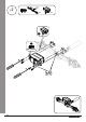
g3a x2 x1 x1 3 M2 x 14mm 2 1 NOTICE: Ensure the driveshaft slides together smoothly. HINWEIS: Sicherstellen, dass die Antriebswelle leichtgängig mitläuft. REMARQUER : assurez-vous que l’arbre d’entraînement s’enclenche doucement. AVVISO: accertarsi che l’albero di trasmissione si muova insieme liberamente. 1.
g3b x2 x1 x1 5 6 4 NOTICE: Ensure the driveshaft slides together smoothly. HINWEIS: Sicherstellen, dass die Antriebswelle leichtgängig mitläuft. REMARQUER : assurez-vous que l’arbre d’entraînement s’enclenche doucement. AVVISO: accertarsi che l’albero di trasmissione si muova insieme liberamente.
g4a x1 x1 x1 x2 1 M2 x 20mm 2 M2 1.
g4b x1 x1 x2 x1 3 M2 x 20mm 4 M2 22
h1 x1 x4 x1 x1 2 1 M3 x 14mm 4 M3 x 14mm 3 1.
h2 x4 x1 x4 1 M4 24
i1 x1 x4 x4 x4 1 2 M2 x 6mm Tip: Use zip ties to secure the excess wiring to the chassis. Tipp: Kabelbinder zum Sichern der überschüssigen Kabel an der Karosserie verwenden. Conseil : utilisez des colsons pour fixer l’excédent de câble au châssis. Consiglio: utilizzare fascette per assicurare i cavi in eccesso al telaio. 1.
i2 x1 x2 x1 x1 x2 x1 3 2 1 5 4 CH 2 ESC CH 1 Steering Servo B/C LEDs 26
1 j1 x1 x4 x2 x2 x1 x4 2 4 3 M2.6 x 11mm 1.
EN STEP 3: PAINT AND STICKER THE BARRAGE BODY SHELL 1. Clean the inside of the Barrage® body shell using a small amount of water and dish soap. Thoroughly rinse and dry the body shell with a cloth towel. 3. Paint the inside of the Barrage body shell. 4. Once the paint is completely dry, remove the over-spray film from the outside of the body and the window masks from inside the body. 5. Using the chart below, apply the windows, grill, head lights, and tail lights.
EN STEP 5: SET UP THE RADIO SYSTEM 1. 2. 3. 4. Remove the battery cover from the transmitter. Install four AA batteries as shown. Re-install the battery cover. Review the transmitter controls (below). BINDING The included transmitter and receiver are bound at the factory. If you need to rebind, follow the instructions below. The transmitter and ESC are bound at the factory. If you need to rebind, follow the BINDING instructions.
EN STEP 6: DRIVE 1 Power on the transmitter. 2 3 Power on the ESC. Drive! WHEN YOU ARE FINISHED 1 2 Power off the ESC. Power off the transmitter. Remove and recharge the battery pack. 3 ELECTRONIC SPEED CONTROL (ESC) Connecting Calibrating 1. Connect the RED (+) ESC wire to the RED (+) motor wire. 2. Connect the BLACK (–) ESC wire to the BLACK (–) motor wire. Ensure proper ESC function by calibrating the ESC to your transmitter inputs.
EN TROUBLESHOOTING GUIDE Problem Short Run Time Sluggish Action Controls Reversed Motor/ESC overheat Does Not Operate Poor Range The system will not connect The receiver goes into failsafe mode a short distance away from the transmitter The receiver quits responding during operation Receiver and transmitter are not bound Vehicle moves forward or backward without input from user Car does not drive straight No steering or lack of steering No throttle or lack of throttle Clicking noise in transmission are
EN LIMITED WARRANTY What This Warranty Covers Horizon Hobby, LLC, (Horizon) warrants to the original purchaser that the product purchased (the “Product”) will be free from defects in materials and workmanship at the date of purchase.
EN WARRANTY AND SERVICE CONTACT INFORMATION Country of Purchase United States of America European Union Horizon Hobby Contact Information Horizon Service Center (Repairs and Repair Requests) servicecenter.horizonhobby.com/RequestForm/ Horizon Product Support (Product Technical Assistance) productsupport@horizonhobby.com 877-504-0233 Sales websales@horizonhobby.com 800-338-4639 Horizon Technischer ServiceHorizon Sales: Horizon Hobby GmbH service@horizonhobby.
IT Replacement Parts List • Teileliste Part Number English Deutsch DYNS1206 Tazer 390 Motor Motor: Tazer 370 DYNS2210 WP 60A FWD/REV Brushed ESC WP 60A Bürstenregler Vorwärts/rückwärts ECX13002 2.4GHz Transmitter, 2-Channel V3 2.4GHz 2 Kanal Sender V3 ECX13003 2.4GHz Receiver WP, 4-Channel V3 2.
IT Liste des pièces de rechange • Elenco dei ricambi Part Number Français Italiano DYNS1206 Moteur: Tazer 370 Motore: Tazer 370 DYNS2210 WP 60A Contrôleur à balais avant/arrière WP 60A ESC con spazzole avanti/indietro ECX13002 2.4GHz Emetteur 2 voies, V3 2-Ch trasmettitore, V3 ECX13003 2.4GHz Récepteur étanche 2 voies V3 2.
IT PARTS DIAGRAM | EXPLOSIONSZEICHNUNG | VUE ÉCLATÉE DES PIÈCES | ESPLOSO DEL MODELLO CON REFERENZA PEZZI ECX210010 - Clear / transparent / transparente / trasparente ECX1048 ECX211019 ECX1048 ECX220009 ECX211019 ECX211014 ECX41006 ECX41004 ECX41006 ECX1060 ECX41004 ECX1060 62
ECX216003 ECX211021 DYNS2210 1.
64 ECX224000 ECX216003 ECX224000 ECX222000 ECX216003 ECX216003 ECX212009 ECX212010 ECX221000 FRONT AXLE | VORDERACHSE | HINTERACHSE | ASSE ANTERIORE ECX217001 ECX216003 ECX222000 ECX212020 ECX222002 ECX216003 ECX212028 ECX217001 ECX216003 ECX212027 ECX217001 ECX216003 ECX212021 ECX221000 ECX212027 ECX217001 ECX221000 ECX212027 IT PARTS DIAGRAM | EXPLOSIONSZEICHNUNG | VUE ÉCLATÉE DES PIÈCES | ESPLOSO DEL MODELLO CON REFERENZA PEZZI
DYNS1206 1.
ECX01011 www.ecxrc.com © 2017 Horizon Hobby, LLC. ECX, the ECX logo, Barrage, Dynamite, Speedpack, Prophet, Tazer, EC3 and the Horizon Hobby logo are trademarks or registered trademarks of Horizon Hobby, LLC. The Spektrum trademark is used with permission of Bachmann Industries, Inc.