
Datasheet


Tel: (416) 754 - 3322
Series 516
Total
Number of Contacts
020,
038, 056, 090 or 120
Contact
Code
1, 2
Description & Tail Size Tail Length "G"
00
0 No Contacts Assembled — —
50
0 Wire Hole .110 x .024 (2.79 x 0.61) .245 (6.22)
52
0 P.C. Tail .025 x .024 (0.64 x 0.61) .215 (5.46)
54
0 Wire Wrap.050 x .024 (1.27 x 0.61) .600 (15.24)
54
1 Wire Wrap.026 x .024 (0.66 x 0.61) .620 (15.75)
54
2 Wire Wrap.050 x .024 (1.27 x 0.61) .790 (20.07)
Style
and Material
3
Style Insulator Material
1 Plug Green Diallyl Phthalate
2 Receptacle Green Diallyl Phthalate
3 Plug Grey Polycarbonate
4 Receptacle Grey Polycarbonate
5 Plug Green Polyester
6 Receptacle Green Polyester
Cover
Code
4, 5, 6, 7
Description
0 No Cover Assembled
1 Plastic Cover, Top Entry Standard Clamp
2 Plastic Cover, Side Entry Standard Clamp
3 Plastic Cover, Top Entry Large Clamp
4 Plastic Cover, Side Entry Large Clamp
5 Metal Cover, Side Entry
6 Metal Cover, Top Entry
Hardware
Code
8
Description
0 No Hardware Assembled
1 Actuating Screw and Polarizing Hardware
2 Locknut and Polarizing Hardware
5 Actuating Screw with No Polarizing Hardware
6 Locknut with No Polarizing Hardware
Ordering
Code Notes
1) Crimp contacts are also available for the 516 series connectors.
Contacts
may be ordered separately for pre-wired or select
position
assembly.
Part
Number Description Silhouette
516-290-50
0 Wire Hole
516-290-52
0 P.C. Tail
516-290-54
0 Wire Wrap
516-290-54
1 Wire Wrap
516-290-54
2 Wire Wrap
516-290-59
0 Crimp - Loose
516-290-59
1 Crimp - 1800 Contacts
per
reel
Page 90
516 SERIES ORDERING CODE
Example Part Number 516 - 038 - 500 - 2 1 2
Series
Total
Number of Contacts
Contact
Code
Style
and Material
Cover
Code
Hardware
Code
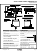
516 SERIES RACK & PANEL CONNECTOR
Plug and Receptacle
FEATURES
● UL Recognized
● .150 (3.81) Contact Spacing x .130 (3.30) or .150 (3.81) Row
Spacing
with Staggered Grid
● Plug and Receptacle in 20, 38, 56, 90 or 120 Contact Sizes
● Edacon Hermaphroditic Contact Mating Design
● Contact Termination Options include Crimp, P.C. Tail, Wire
Hole
and Wire Wrap
● Mating and Unmating Simplified with use of Actuating Screws
● Optional Covers with Side or Top Entry Cable Clamp in
Plastic
or Metal Material Available for all Connector Sizes
● Versatile Metal Cover Design permits Assembly or Disassembly
After
Cabling is Complete plus Cable Entry Style Flexibility
● Actuating Screws, Locknuts, Polarizing Hardware, Covers
and
Contacts Suitable for either Plug or Receptacle
● Polarizing Hardware Adjustable for 288 Mating Combinations
● Tools Available for Contact Installation, Removal and
Crimping
and Polarizing Changes
SPECIFICATIONS
◆ Insulator Material: Diallyl Phthalate or Thermoplastic Polyester,
UL
94V-0, Colour: Green, or Polycarbonate, Colour: Grey
◆ Contact Material: Phosphor Bronze Alloy CA-510
◆ Contact Plating: Gold over Nickel for Entire Contact
◆ Cover Material: Polycarbonate, Colour: Green, or Die-Cast
Zinc,
Finished with Grey Enamel Paint
◆ Current Rating: 8.5 Amperes
◆ Contact Resistance: 10 Milliohms Maximum
◆ Dielectric Withstanding Voltage: 2000 V AC rms at Sea Level
◆ Insulation Resistance: 5000 Megohms Minimum
◆ Operating Temperature: -65 to +105 Degrees C
◆ Insertion and Withdrawal Force: 2 to 16 oz (0.56 to 4.45 N)
per
Contact Position
Continued on next page