
Datasheet

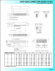
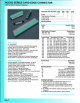
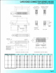
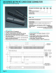
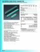

325 SERIES CARD EDGE CONNECTOR
.
100
''
(2
.
54mm)
Contact
Spacing
,
Accepts
.
125"
(3.18mm)
Thick
Board
.1
00 (2.54) Contact Spacing x .300 (7 .62) Row Spacing
Accepts .125 (3.18) Nominal Thickness P.C. Board
High Profile
Insulator Body, .600 (15.24)
Contact Termination Options include P.C. Tail, Wire Hole &
.025 (0.64) Square Wire Wrap
Single
or
Dual Row Configurations
Variety
of
Mounting Options
Accepts
In-Contact Polarizing Keys
Automatic Wire Wrap Positioning
Ho
les
Insulator Material: Polyphenylene Sulphide,
UL
94V-O.
Co
lour: Green
Contact Material: Copper, Nickel, Tin
Al
loy CA-725
Contact
Plating: Gold on the Mating Area, Tin on the
Contact Tails, Nickel Underplate
Current Rating: 3 Amperes Continuous
Contact
Resistance: 10 Milliohms Maximum
Dielectric Withstand
in
g Voltage: 1200 V AC rms at Sea Level
Between Adjacent
Contacts
Insulation Resistance: 5000 Megohms Minimum
Operating Temperature:
-65
to
+125 Degrees C
Insertion
Force: 16 oz (4.45 N) Maximum per Contact Pair
when Tested with a .135 (3.43) Thick Gauge
Withdrawal Force: 1
oz
(0.28 N) Minimum
per
Contact Pair
When
Tested with a .115 (2.92) Thick Gauge
Page25
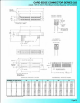
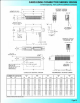
Example Part Number 325
-122
- 520 - 2 09
Ser
ies
T T
Total
N
um
ber
of
Contacts
-----'
Contact Code -
Contact
Rows
-------------~
Mo
untl
ngOpt
ions
------------~
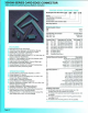
Series 325
Total Number
of
Contacts
1
005, 006,
.•.
061
010, 012, ... 122
Contact Rows
Single Row
Dual Row
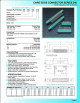
Contact Code Description &
Tail
Size
Tail
Length
"G"
500
Wire
Ho
le .050 x .025 (1.27 x 0.64) .260
(6
.60)
520
P.C. Tail .025 Square (0.64 Square) .
175
(4.45)
540
Wire Wrap .025 Square
(0
.64 Square) .560(14.22)
Contact Rows
1
2
Mounting0ptlons
2
01
07
08
09
O
rdering
Code Notes
Description
Single Row
Dual Row
Description
No Mounting Lugs
M~0.5
Metric
Threaded
Inserts
#4-40
Unified Threaded Inserts
.160 (4.06)
Dia. Mounting Holes
1)
All connector sizes
up
to
61
contacts sing
le
row
/122
contacts dual row are available upon request.
2) For details
of
the mounting options, refer
to
page 63.
-