
Datasheet
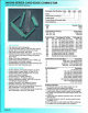
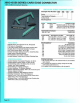
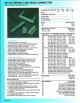
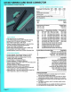

307/357 SERIES CARD EDGE
CONNECfOR
.156" (3.96mm) Contact Spacing
CSA Approved and UL Recognized
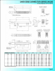
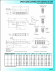
.156 (3.96) Contact Spacing x
.200
(5
.08) Row Spacing
Accepts
.062 (1.57) Nominal Thickness P.C. Board
Low Profile
Insulator Body, .460 (11.68)
Contact Termination Options
include
P.C
. Tail, Wire Hole,
Wire Wrap,
90
Degree & Extender Board Bends
Single
or
Dual Row Configurations
Large Variety
of
Mounting Options
Pre-assembled
Card Guides Available
Accepts Between Contact and In-Contact Polarizing Keys
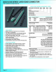
Insulator Material: Thermo
pl
astic Polyest
er,
UL
94V-O
Contact Material: Copper,
Ni
ckel, Tin
Al
loy CA
-72
5
Contact Plat
in
g: Gold on the Mat
in
g Ar
ea,
Tin on the
Contact
Tails, Nickel U
nd
e
rp
la
te
Current Rating: 5 Amperes Continuous
Contact Resistance: 1
0 Milliohms Maximum
Dielectric Withstanding Voltage:
1800
VAC
rms at Sea Level
Between Adjacent Contacts
Insulation Resistance: 5000 Megohms Minimum
Operating Temperature:
~5
to +105 Degrees C
Insertion
Force: 16 oz (4.45 N) Maximum per Contact Pair
when Tested
with
a .070
(1
.78) Thick Gauge
Withdrawal Force:
1
oz
(0.28
N)
Minimum per Contact Pair
when Tested with a
.054 (1.37) Thick Gauge
Orderi
ng
Code Notes
1)
All connector sizes up
to
44
contacts single row I 88 contacts
dual row are ava
il
able upon r
eq
uest.
2)
For contacts with overall tin plating, change t.he first digit of
the contact code from 5 to 4.
3) Single row contacts that read both sides
of
the daughter
board
are
phosphor bronze
CA
-510 material with entire
surface plated gold over
nickel.
4) For detans
of
the extender board
and
90
degree bends, refer
to page
61
.
5)
Switching contacts, assembled in specific contact positions,
are
available upon request.
6)
For details
of
the mounting options. refer
to
page 63.
Pag
e35
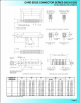
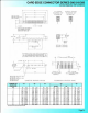
Example Part
Number
307 • 044 - 520 - 2 02
Series
--_____l
T T J
Total Num
be
r of Con
ta
cts
-
Contact Code
Contac
tRow
s
--------------------------.....J
Mounting Opti
on
s
---------
------------
--.....J
Series
307
357
Insulat
or
Colour
Green
Black
Total Number
of
Contacts'
C
on
ta
ct
Rows
Single Row
Dual Row
006. 007,
..
. 044
012, 014 .... 088
Conta
ct
Code
u-.
• De
sc
rip
tio
n & Ta
il
Size Tail Len
gt
h "G"
Single Row Contacts - Read One Side
of
Daughter Board
505
Wire Hole.087 x .013
(2
.21 x 0.33) .282 (7.16)
525
P
.C.
Tail .046 X .013 (1.17 x 0.33) .213 (5.41)
527 P.C.
Tall .046 X .013 (1.17 X 0.33) .358
(9
.09)
5
31
P.C. Tail .023 x .013 (0.58 x 0.33) .213 (5.41)
545
Wire Wrap.046 X .013
(1
.
17
X 0.33) .708(17.98)
547
WlreWrap.046x .
013(
1.17 x 0.33) .520(13.21)
558
90
Degree Bend (Code 545 Contacts)
559
90 Degree Bend (Code 527 Contacts)
Sing
le
Row
Contacts
- Read
Both
Sides
of
Daughter Board
501
Wire Hole.089 x
.01
4 (2.
29
x 0.36) .
21
3 (5.
41
)
521
P.C.
Tail
.046 X .014 {1.17 X 0.36) .213 {5.
41
)
541
Wire Wrap.046 x .
014
(1.17 x 0.36) .495(12.57)
553
90
Degree Bend (Code
521
Contacts)
554
90
Degree Bend (Code 501 Contacts)
557
90
Degree Bend (Code
541
Contacts)
Dual Row
Conta
cts - Read
Both
Sides
of
Daughter Board
500
Wire Hole.087 x .013
(2
.21 x 0.33) .282
(7
.16)
520
P.C. Tail .
046)(.013(
1.1
7x0
.33) .. 213 (5.41)
522
P
.C.
Tail .046 X .013 (1.
17
X 0.33) .3
58
(9.09)
524
P.C. Tall .023 X .013 (0.
58
x 0.33) .213 (5.41)
540
Wire Wrap.046 X .013 (1.17 X 0.33) .708(17.98)
542 Wire
Wrap.046 x .013 (1.17 x 0.33) .520(13.21)
555
Extender Board Bend (Code 500 Contacts)
556
Extender Board Bend (Code 520 Contacts)
558
90
Degree Bend (Code 522 and 540 Contacts)
559
90 Degree Bend (Code 522 and 540 Contacts)
560 Extender Board Bend (Code 522 Contacts)
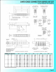
Contact Ro
ws
1
2
Mounting
Options•
01
02
03
04
07
08
12
58
68
78
D
esc
ri
pt
i
on
Single Row
Dual Row
Descri
pti
on
No Mo
un
ti
ng
Lugs
.128
(3
.25) Dia. Mounti
ng
Holes
.116 (2.95)
I.
D. Floating Eyelets
.156 (3.96) Dia. Mounting Holes
M3-0.5 Metric Threaded Inserts
#4-40
Unified Threaded Inserts
.1
28
(3.
25) Dia. Side Mounting Holes
.468 (
11
.89) Offset
card
Guides
.
344
(8.74) Offset Card Guides
In-Line Card Guides