~s COMPLIANT ISO 9001 FM 63475 GROUP A world class manufacturer of high quality electronic connectors with offices in United States England Taiwan hina EDAC components are available through a worldwide network of Distributors and Manufacturers Representatives For the contact name and number of an EDAC representative In your area please refer to our web site at [ http://www.edac.
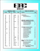
GROUP NUMERICAL INDEX Series Page 100 103 105 106 205 206 207 237 241 243 243Guide 245 246 301 73 73 73 73 72 72 72 302 303 305 306 307 307Guide 308 3 10 315 316 3 17 317Guide 321 15 39 31 33 35 66 72 49 31 33 41 66 50 51 52 72 322 323 324 325 327 330 333 334 336 337 338 339 340 341 342 345 345Gulde 72 72 59 65 72 72 14 25 54 72 43 72 45 37 47 27 24 19 21 17 66 Series 345Guide 345Tools 346 346Guide 349 355 356 357 366 366Guide 379 384 387 389 391 392 395 395 98 Pln·AT 396 399 TABLE OF CONTENTS
CONNECTOR APPLICATIONS Edac connectors are used around the world in a wide variety of applications. The Edac product line includes a broad range of card edge connectors together with rack & panel and metal to metal interconnect systems, application tooling and card guide components.
CONNECTOR APPLICATIONS METAL TO METAL AND RACK & PANEL CONNECTORS When ultra reliable interconnections are required, use of our metal to metal contact system is suggested. Either standard sized connectors can be specified, or a customer's own contact pattern can be accomodated using individual components mounted di"rectly to the printed circuit board. The principle of the Edacon metal to metal contact is shown below.
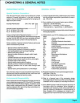
ENGINEERING & GENERAL NOTES ENGINEERING NOTES Plastic Moulding Materials Contact Finish (Plating & Gold Inlay) Edac offers a wide range of insulator materials Including The stahdard contact finishes offered include: polyester, diallyl phthalate, polyphenylene sulphide, polycarbonate and nylon. Card guides are moulded in 1) Selective plating- nickel overall followed by gold on the polyester orpolycarbonate and polarizing keys are moulded contact mating area and tin alloy on the contact tails in nylon.
ENGINEERING & GENERAL NOTES GfJIIER Over the past 40 years, Edac has manufactured a wide selection of special connectors. In the part numbering system, they are identified as special by the last group of digits in the part number. Example Part Number 345 - 072- 520 - 3 05 Special Variation Identification Code _____] No. 3 - for Series 100 to 438 No. 9- for Series516 to 746 Unique Listing Code for Special Connector - - - - ' This number is assigned by Edac.
00 SERIES GROUP Compliant Pin Card Edge Connectors -Mate Contact Spacings of .100 (2.54), .125 (3.18) and .156 (3.
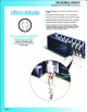
ULTRA-MATE CARD EDGE CONNECTOR TOOLS Compliant Pin Connector Installation, Contact and lnsulatior Removal I: TnA C:T I Connectors received by the customer are ready for installation into the circuit board. The flat rock insertion technique requires a press and adequate support for the circuit board. Once the number of contacts to be pressed into the board together has been determined, the press tonnage should be calculated at approximately 30 pounds (134 N) per contact.
745 SERIES ULTRA-MATE CARD EDGE GONNECTOR .100" (2.54mm) Contact Spacing, Compliant Pin 745 SERIES ORDERING CODE J Example Part Number 745 - 100 - 520 - 2 06 \\\\\\\\\\\\\\\\\\\\\\\\\\\\\\~~~ T Series Tot al Number of Contacts - - - - - ' Contact Code Contact Row s - - - - - -- - - - - - -...J Insulator O ptions _ _ _ _ _ _ _ _ _ _ _ _ _.J Series Total Number of Contacts ' 005, 006,...075 010, 012,...150 l.f-{.J ' I I I 'lo/../, . • ,, I ""'·1/' I I I • "'/•f-t j .. , ' ..• f.
ULTRA-MATE CARD EDGE CONNECTOR SERIES 745 Compliant Pin, Contact Spacing .100" (2.54mm) SE.CTIONS ' Y' - ' Y' CONTACT ROWS & INSULATOR OPTIONS 'C' - - - - --1 j_ .260 (MO) T ~CUIAA I'QHT ()I! .J35 (8.5 1) •yu CODE 101 7 25 SO!IES _ _ _J ~:g~ CODE 201 CODE 101 725 SERJES 745 SO!IES CODE 201 7 45 SERJES (\~7) 725 SEIIJES .-420. ( >0.67) ~( ' G' CODE 106 ~·r·--1 CODE 206 MAK£ BErofl£ !lf\tM {W.U) POtHI COHffoCTS NOT AVAILA8LE F'OR 725 SVOES CODE 201 I ~ -0 CODE 206 - f- .
746 SERIES ULTRA-MATE CARD EDGE CONNECTOR .125" (3.18mm) Contact Spacing, Compliant Pin TT Example Part Number 746 - 070 - 525 - 6 01 Series - - - - - T' Total Number of Contacts - Contact Code Contact Rows & Card Slot Depth - - - - - - - ' Insulator Optlons- - - - - - - - - - - - - . . . J Series 746 Total Number of Contacts ' 005, 006,...060 010, 012,... 120 Contact Code 2 520 525 527 540 541 545 CSA Approved and Ul Recognized .125 (3.18) Contact Spacing x .250 (6.35) Row Spacing Accepts .062 (1 .
ULTRA-MATE <::ARD EDGE CONNECTOR SERIES 746 Compliant Pin, Contact Spacing .125" (3.18mm) SECTIONS ' Y ' - ' Y ' CONTACT ROWS & INSULATOR OPTIONS 1----- :~:: Sir~Glt ------1'1 ~tl' ·---=- P" m.r.c f« o.ton.. I (M•) _cOIIToiCT POIIIT .I • u Ro- V..-.iona t.IOJt R~ Soetup Sp~W;t Otpendif'\9 on tl'lt ~eotlofl . Corti~ ~'"' .420 .~50 ( 10.67) CNtl) (13.97) SI.D _l sun ACCePTS M! (o.J1) oo oro 0 .
737 SERIES ULTRA-MATE CARD EDGE CONNECTOR .156" (3.96mm) Contact Spacing, Compliant Pin T Example Part Number 737 - 044 - 520 - 206 Series - - - - - - ' T Total Number of Contacts Contact Code Contact Rows Series 737 Contact Code 2 520 522 525 540 541 545 Insulator Material: Thermoplastic Polyester. UL 94V-O, Colour: Black Contact Material: Copper, Nickel, Tin Alloy CA-725 Contact Plating: 30 Microinches (0.
ULTRA-MATE CARD EDGE CONNECTOR SERIES 737 Compliant Pin, Contact Spacing .156" (3.96mm) SECTIONS 'y"-" Y • CONTACT ROW OPTIONS 1~-·_ _ :::_ _--1,1 M~L~ E ,-- • (a.H9) _.1_ .1_ c>llo sun .m (•u>) ~.eo> J tMO SLOT .CCt'J'!S .OSo! (I.J7) ro Ol D (I ?8) llJS(8SI) HICH I'Oltll CODE 1 06 'Y" --- ....! r • CODE 206 -r ~I (I 658) CONI/CS I ·~ ..,. .. ._.... G I 02S (0 6<1 , .100 ....L (>!><] -t F t.
745 SERIES {98 PIN-AT) ULTRA-MATE CARD EDGE CONNECTOR .100" (2.54mm) Contact Spacing, Compliant Pin J Example Part Number 745 - 098 - 520 - 900 T Series - - - - - - J T Total Number of Contacts Contact Code Variation Code Series 745 - -------------_..J -------------------------- Total Number of Contacts 098 Contact Code See 745 Series for Available Contact Options and "G' Dimension Variation Code Description 900 Card Slot Barrier with .645 (16.38) Full Height Ends 904 Card Slot Barrier with .
EISA CARD EDGE CONNECTOR SERIES 301 Contact Spacing .050" (1 .27mm) Part Number ' 301 - 188 - 520 - 201 T I J Series Total Number of Contacts Contact Code Style- - - - - - - - - - - - - - - ' EISA or ISA (IBM XT/AT} Daughter Boards Accommodated with Bi-Level Contact Points and Card Slot Depths .050 (1.27} Contact Spacing with Staggered Tail Bend Results in 4 Rows at .100 (2.54) Spacing Accepts .062 (1.57} Nominal Thickness P.C.
302 SERIES MCA CARD EDGE CONNECTOR .050"(1 .
MCA CARD EGDE CONNECTOR SERIES 302 Contact Spacing .050" (1 .27mm) P/N 302-132-520-201 SECTION THROUGH CONTACT POSITION ~ .100 12.51) "'' I~SI) 200 (>oa) .JOO (M2) P/N 302-182-520-201 .00> (1,111 .1>50 (1.27) ~ r-------I l .... I ... (IJill) --------------1~ l.l'l:l \~.2;.)) - - - - - j <••·") oon~ IICW Ml> tOlOSS SfCTON ~ VI.AA IQ 112 ~-0 _l Jl2 N C
345/395 SERIES CARD EDGE CONNECTOR 100" (2.54mm) Contact Spacing TT Example Part Number 345 - 050 - 520 - 2 02 Series - - - . - . J T To~INumberofContac~ -- Contact Code Contact Rows and Insulator Style- - - - - - _ _ J Mounting Options --------------~ Series 345 395 Total NumberofContaw • 005, 006....072 010, 012,...144 CSA Approved and UL Recognized .100 (2.54} Contact Spacing x .200 (5.08) Row Spacing Accepts .062 (1.57) Nominal Thickness P.C. Board High Profile Insulator Body, .600 (15.
CARD EDGE CONNECTOR SERIES 345/395 Contact Spacing .100" (2.54mm) C ~E \'RAP HQl£ Wl $.0! " i'.. I I J/0 ,~ Q) A' SECTIONS "THROUGH "B' CONTACT POSITION "C' ~ e Jl SINGLEAOW I LW 1-$- I' -mJ I CAOQ !ll.OT t<:C!P)> {I Sll 10 010 ~ 18~ os.o 1HCK P.C, 90.1110, ~ --- • D" - - - - 1 1- ·s~·-- f:\'tN HUUBERto 9DE or CON~EC1<:4l (J, 4) 110 r 1 '-'-t.....,L- - - - - - - _,r--1+'-' 7!>0 (6.1.5) V !>I DO "G' 110 (2.79) o-1 wrs I _I L .0JO (0.
341/391 SERIES CARD EDGE CONNECTOR 100" (2.54mm) Contact Spacing 341 /391 SERIES ORDERING CODE T Example Part Number 341 • 062 - 520 - 2 02 Series Total Number of Contacts _T_____j_I - Contact Code Contact Rows - - - -- -- - - -- --..J MountlngOptlons - - - - - - - - -- ---..J Series 341 391 Total Number of Contacts ' 005, 006,... 060 010, 012,...120 UL Recognized .100 (2.54) Contact Spacing x .140 (3.56) Row Spacing Accepts .062 (1 .57) Nominal Thicl
CARD EDGE CONNECTOR SERIES 341 /391 Contact Spacing .100" (2.54mm) I .I I .).. .I. b ~rr.> BETWEEN CONTACT POLARIZING t-JI8 -$- Jl{ I 0\RD slor IN-CONTACT POLARIZING KEY PIN J21· !• (> Jl) IQ 070 (I 10) l>4 l'r< U~ IQ 27 (OD {10.16) 24/>t RN k 0\'£• .., (11 ,., Jo-r-r~h-' SECliON THROUGH ~ bl:fb==min:n::rm:r!J'lJ'ml"1TT11'1Il"'l'11"ll''ll===FI I CONTAC1 POSI110N l .l 25 (l.18) X .020 (0~0 " ftE Hlltf .
342/392 SERIES CARD EDGE CONNECTOR .100" (2.54mm) Contact Spacing Series Total Number of Contacts - -- - - - L T Contact Code - Example Part Number 342 - 100 - 541 - 2 02 T Contact Rows ---------------~ Mounting Options --------------------------1 Series 342 392 Insulator Colour Green Black Total Number of Contacts 005, 006, ...058 010, 012....116 UL Recognized .100 (2.54) Contact Spacing x .200 {5.08) Row Spacing Accepts .062 (1.57) Nominal Thickness P.C. Board High Profile Insulator Body, .
CARD EDGE CONNECTOR SERIES 342/392 Contact Spacing .100" (2.54mm) 1 - - - - - - - ' A'' - - - - - - - 1 IN-CONTACT POLARIZING KEY ··a· BETWEEN CONTACT POLARIZING KEY r·c·~ I ! .J10 llfillil- ·:ili:tmJ ·r> ~~ • J!UI W~~ c;'"tiWJl CA~ 1-9- SI.OI I.CC0'1S OS' 1 .l7 I I I I 1------------- - - I 1210 (6 8SJ .>.
395 SERIES (98 PIN-AT) CARD EDGE CONNECTOR .100" (2.
CARD EDGE CONNECTOR SERIES 340 Contact Spacing .100" (2.54mm) T Example Part Number 340 - 050 - 523 - 2 02 Series- - - ' T Total Number of Contacts T - Contact Code Contact Rows ----------------------------~ Mounting Options ----------------------------'Series 340 Total Number of Contacts 1 005, 006,... 060 010, 012,...
325 SERIES CARD EDGE CONNECTOR .100'' (2.54mm) Contact Spacing, Accepts .125" (3.18mm) Thick Board T Example Part Number 325 -122 - 520 - 2 09 T Series Total Numbe r of Contacts- - - - - ' Contact Code Contact Rows -------------~ MountlngOptions ------------~ Series 325 Total Number of Contacts 1 Contact Rows 005, 006,.•.061 010, 012 ,...122 Contact Code 500 520 540 Single Row Dual Row Description & Tail Size Wire Hole .050 x .025 (1.27 x 0.64) .260 (6.60) P.C. Tail .025 Square (0.64 Square) .
CARD EDGE CONNECTOR SERIES 325 ccepts .125" (3.18tnm) Thick Board, Contact Spacing .100" (2.54mm) 'A' 'B' 'C' SECTION THROUGH CONTACT POSITION .•90 (!VB) CNO SU)f ACCO'tS 11~ (2.91J 10 Ill> (.1 lr.ACts ral ;>O;Clt f«O\W C0Hf€CTORS On f'IOI ILt.litKD 5IX I- ~'-" .!00 (15.2' ) I J1t 1162) I ~a~~~~~~~==~~======~~~~ 'G' OJG L x CM (07A 1- I IL21) •OO (2-S<) E'l tfl '6' 1~ (),et) r;..:l 100\.
339/389 SERIES CARD EDGE CONNECTOR .100" (2.54mm) Contact Spacing (Bellows Contacts) Example Part Number 339 Series - Joso -T520 - 2 02 -------....1 ----.....l Total Number of Contacts Contact Code _ _ _ _ _ _ _ _ _ ____J Contact Rows and Insulator Style ------....J Mounting Options - - - - - - - - - - - - - - - ' Series Insulator Colour 339 389 Green Blacll Total Number of Contacts ' 005.006 ....072 0 10,012... 144 CSA Approved and UL Recognized .100 (2.54) Contact Spacrng x .200 (5.
CARD EDGE CONNECTOR SERIES 339/389 Contact Spacing .100" (2.54mm) (Bellows Contacts) SECTIONS THROUGH CONTACT POSITION ' A' (: WIA£ WFQ.P HOlE 11'0 Si.O! • B' ~ ~ J ~ ' ) 70 . +0) I , c· ' 1.'1: j"--1\1 1-" !4?- CARD SlOl N:tErn .064 (1.l7) 10 .010 (1,)0) llflCK P.C. 90AAOS ···~ r--------'D'--------~ :Clf"';C0~1Hiii:HE~CT~OI!;7 .610 (1$.50) ~ I e...) (6,j$) I 150 (4 ~7) OR 120 (3,1)$) Off'S£T LUGS • G' (1. • · &, _L FliiSit WOUN'Iti
346/396 SERIES CARD EDGE CONNECTOR .125" (3.18mm) Contact Spacing T Example Part Number 346 • 056 - 540 • 8 02 Series Total Number of Contacts T T Contact Code - - - - - - - - - - - . . . . 1 Contact Rows and Insulator Style--- ------' Mounting Options - - - -- - -- - - - - - - ' Series 346 396 Insulator Colour Green Black Total Number of Contacts 1 005, 006,...050 010, 012,...100 CSA Approved and UL Recognized .125 (3.18) Contact Spacing x .250 (6.35) Row Spacing Accepts .062 (1 .
CARD EDGE CONNECTOR SERIES 346/396 Contact Spacing .125" (3.18mm) II At 1.11().i.A,.t '"" ~flt ~OH " " ' I 1 "- ~~I I f•.•o) 5E.CnONS n-tROlJGH ·e·· ··c , Wl f'05lt10Hr\G SI. Of "t-0 ili I CONTACT POSinON ~ ' I{ ~ I )) CAll OSLOI lot((PfS~~ (.J 10 .070 (1.18) ll!ICJI P.C. BQ· 2<10-.
305/315/355 SERIES CARD EDGE CONNECTOR .156" (3.96mm) Contact Spacing TT Example Part Number 305 - 056 - 521 - 2 04 Series Total Number of Contacts _ __ _.J Contact Code - lnsulator Style - - - - - - - - - - - - - . . . 1 ft'ountl ng Optlons - - -- - - - -- - - - - - 1 Card Slot Length Standard Length per MIL-C-21097 .020 (0.51) Shorter than Standard Standard Length per MIL-C-21097 Series Insulat or Colour 305 Green Green 315 Black 355 Total Number of Contacts 012, 014,...
CARD EDGE CONNECTOR SERIES 305/315/355 Contact Spacing .156" (3.96mm) r----------'A'----------~ ·e· BETWEEN CONTACT IN-CONTACT POLARIZING KEY ~~c· POLARIZING KEY P/N Jo1-J'> - -~~ (B 11) UP 10 - :.00 (1) 10) 26{S6 • O> L I H mJff-- ~~ Hl1 i F 1- 155 (!Ill) ~· SECTIONS lHROUGH CONTACl POSillON l:±:!i±=='1l"IT'IT'-olf'~_,......,......
306/316/356 SERIES CARD EDGE CONNECTOR .156" (3.96mm) Contact Spacing J Example Part Number 306 - 022 - 521 - 178 Series --.I T Total Number of Contacts Contact Code Mounting Options - -- - -Series 306 316 356 T - - - -- - - - - - ' Insulator Colour Card Slot Length Green Standard Length per MIL.C-21097 Green .020 (0.51) Shorter than Standard Black Standard Length per MIL-C-21097 Total Number of Contacts • 006, 007,. ..
CARD EDGE € 0NNECTOR SERIES 306/316/356 Contact Spacing .156" (3.96mm) ~------------ ' A'--------------1 ! - - - - - - '' 8'- - - --t IN-CONTACT BETWEEN CONTACT POLARIZING KEY POLARIZING KEY r--·c·~ COO SLOT !GQEPlS P/W lJ&-?4~-m P/N JDH4~- Jl8 ir-"D' ~ I 054 (tJ1) ro 010 (Ill!) lltCK f.C. 81W!D 3<-l (8 "' SiltS Z$" PtH ~ D \1.1~ 1\1\L IIA'I £ ~ aoor wtDilt r:1 .ooo (12.10) I _ - - - - - __ _I •50 (11 68) I .200 (E.
307/357 SERIES CARD EDGE CONNECfOR .156" (3.96mm) Contact Spacing J Example Part Number 307 • 044 - 520 - 2 02 Series - - _ _ _ _ _Tl Total Number of Contacts T - Contact Code ContactRows --------------------------.....J Mounting Options -----------------------.....J Insulator Colour Green Black Series 307 357 Total Number of Contacts' 006. 007,...044 012, 014....088 CSA Approved and UL Recognized .156 (3.96) Contact Spacing x .200 (5.08) Row Spacing Accepts .062 (1.57) Nominal Thickness P.C.
CARD EDGE CONNECTOR SERIES 307/357 Contact Spacing .156" (3.96mm) IN-CONTACT POLARIZING KEY BETWEEN CONTACT POLARIZING KE:Y DUAL ROW CONTACTS SINGLE ROW CA.'i'O 9.0T ACCfPlS DS4 (I 3l) CONTACTS ONt gor OF !l.lll:lll!R llOAAD ro ,o7o ( 1 7&) m.tk Pc 90N1C ..su (&.71) "" ro 17/S. 1'1• ( 12 70) 28/M .. tMII 51)0 .JIXl (7 fi2) CNfD SLOt I '-----------------NUU.SEJl(O SIC{ Of CONNEClOA ' C' SINCL[ ROW CONTACiS ~·a (1.22) X ·~ (3181 tiiJJ:U: ..ou 1----- • £. .. - - - - l ,124 PNlil l.
337/387 SERIES CARD EDGE CONNECTOR .156" (3.96mm) Contact Spacing T·5J24 · 204 :::e:ple Part NumberT - Tota.l Number of Contacts- -- - -' _ Contact Code- - - - - -- - -- - - ' Contact Rows and Insulator Style- - - - - ----' Mounting Options - - - - - - - -- - - -- - ' Insulator Colour Green Black Series 337 387 Total Number of Contacts 006, 007,. ..043 012, 014,.•.086 CSA Approved and UL Recognized .156 (3.96) Contact Spacing x .200 (5.08) Row Spacing Accepts .062 (1.57) Nominal Thickness P.C.
CARD EDGE CONNECTOR SERIES 337/387 Contact Spacing .156" (3.96mm) BETWEEN CONTACT •A• POLARIZING" KEY '8 .. ~ ACttJ%15 •IN .l0&-1<0-}to ~'C" (iJI) TO 070 (1.78) P.C. DllAilO 'D' I I ~~ I { <0) 1 1 I IN CONTACT POLARIZII\IG KEY '8" =:l .600 (•M•) Pftt .H!I-7·o- ~8 _j I . 250 (slS) ,..w..wl L 1 ·~~--~~ ~0 (5,0111 -111 I ' G' ~ ., • ® W llfi: •H0l£ f- -j ,,... .no !4.31) Cffs£1 ; I J SINGLE ROW DUAL ROW .oe• <>~•! ---"E' it - · 160 (l!JB) POHT rY ~OOl!CJ .
303 SERIES CARD EDGE CONNECTOR .156" (3.96mm) Contact Spacing T Example Part Number 303 - 086 - 520 - 202 Series T otal Number of Contacts T ----...J Contact Code MountingOptions- - - - - - - - - - - - - J Series 303 Total Number of Contacts 1 012, 014,...086 Contact Rows Dual Row Contact Code Description & Tail Size Tail Length "G" 520 P.C. Tail .046 x .010 (1 .17 x 0.25) .219 (5.56) UL Recognized .156 (3.96) Contact Spacing x .140 (3.56) Row Spacing Accepts .062 (1 .57) Nominal Thickness P.C.
CARD EDGE CONNECTOR SERIES 303 Contact Spacing .156" (3.96mm) , - - - - - - - - ' A " - - - - - --1 1 - - - - - - ' B " - - - - - ·-1 IN-CONTACT POLARIZING IT oiCCEl'lS 1)5{ (1 l71 10 Q10 (1.78) ruiO( PC 60ARO I L •M (1194) 1~ I t> 1e1 PONI (IJ;) V I ~~~nn~~~~~ ' G' V I V I J.
317 SERIES CARD EDGE CONNECTOR .156" (3.96mm) Contact Spacing T Example Part Number 317 - 072 - 542 - 8 08 T Series Total Number of Contacts- - - - - ' Contact Code ContactRows - - - - - -- -- -- - ----J Mounting Options - - - - - ---------------- - ' - Series 317 Total Number of Contacts ' 006, 007,...043 012, 014 ,...086 .156 (3.96) Contact Spacing x .200 (5.08) Row Spacing Accepts .062 (1 .57) Nominal Thickness P.C. Board High Profile Insulator Body, .720 (18.29) Contact Termination .045 (1 .
CARD EDGE CONNECTOR SERIES 317 Contact Spacing .156" (3.96mm) 1 - - - - - - - - - -' A"- - - - - - - - - - 1 DUAL ROW CONTACTS CODE 542 COOE 540 1 - - - - - - -- · s··--------1 I tf.lf-'-.m (s.-oo) C'MO SlOf I 2<0 (6 ID) PON' « oo~.t« eo'",f.Cl I I ~cm:~~-----------~~~ (I ~~ (• 1<) - , ,., ·c· (11 JO) I or Cl>42 ~ I ,_ .56 ( •.••) '('-------1 1:\1.!1( lP li:PQN'iS l
333 SERIES CARD EDGE CONNECTOR 156" (3.96mm) Contact Spacing Series Total Number of Contacts _ _ __ _. T Contact Code - Example Part Number 333 - 044 - 520 - 2 04 T Contact Rows and Insulator Style ---------l Mounting Options _ _ _ _ __ _ __ _ _ __ ...J Series 333 Total Number of Contacts 1 006, 007,...043 012, 014,...086 .156 (3.96) Contact Spacing x .200 (5.08) Row Spacing Accepts .062 (1.57) Nominal Thickness P.C. Board High Profile Insulator Body, .600 {15.
CARD EDGE CONNECTOR SERIES 333 Contact Spacing .156'' (3.96mm) 'A' ·e~~ ~~=:~·~ I I 370 (9 •~ I I -rAQO SlOf 111 .o1o f.i f.l fi fiffif.l "' "' "' "'iii' "' "' ~JS ( ol!l) ''"'" f.l I~~ os.t ( l JI) r.c SINGLE ROW 001o1111 _j_ DUAL ROW IN-CONTACT POLARIZING KEY P/N I llO (~.05} PANEl lotOUNl I I J60 (u;) tL CVr 4tJ • 0 I .... ' b 0 .200 ().0!) c111 cur 200 (50&) I,QJN[ our 1 . 1:16 (J !~) 0~ ~Ef- D • 0 < "'' • c c • "' ' 0 £ 7 • o::ro er o " J .
336 SERIES CARD EDGE CONNECTOR .156" (3.96mm) Contact Spacing =pie Part Number T-j -5T20 - 8 09 Total Number of Contacts- - - - - - ' Contact Code - - - - - -- - -- - ' Contact ROW81- - - - - - - - - - - - - - ' Mounting Options - - - - - - - - - - - - Series 336 Total Number of Contacts ' 006, 007,...043 012, 014,...086 Contact Rows Single Row Dual Row Contact Code 520 541 Description & Tall Size Tall L.eng1h "G" P.C. Tail .031 Square (0.79 Square) .260 (6.60) Wire Wrap .062 x .031 (1.57 x 0.
CARD EDGE CONNECTOR SERIES 336 Contact Spacing .156" (3.96mm) BETWEEN CONTACT 1 - - - - - - - - -"A' - - - - - - - --1 POLARIZING KEY · s· •cl• • 0' I' I lltj 'I 1- '--1 A-
338 SERIES CARD EDGE CONNECTOR .156" (3.96mm) Contact Spacing J Example Part Number 338 - 044 - 541 - 2 08 T T Series Total Number of Contacts - - - - - - ' Contact Code Contact Rows --------------~ MountlngOptlons - - - - - - - - - - - - - - . . . J Series 338 Total Number of Contacts 010, 015, 018, 022 Of 028 020, 030, 036, 044 or 056 Contact Rows Single Row Dual Row Contact Code Description & Tail Size Tail Length "G" 540 Wire Wrap .045 Square (1.14 Square) .480(12.19) 541 Wire Wrap .
GARD EDGE CONNECTOR SERIES 338 Contact Spacing 156" (3.96mm) 1-- - - - ' A ' - - - - - - 1 BETWEEN CONTACT IN- CONTACT POLARIZING KEY 1 - - - - - · s · - - - --1 p~ POLARIZING KEY Jla-l!0- );8 tA'll SI.OI J.tCIJII~ 05" to J7) r~ .070 (1.78) flliCK P.C (!o!j!b I I ~-- ---- - ---------_I (~oa) POI~l Of COIIT.\C1 .100 (2 54) BAC1< UP SP~NGS LOCAI(Q •N POS
310 SERIES CARD EDGE CONNECTOR . 156" (3.96mm) Contact Spacing 310 SERIES ORDERING CODE T Examp le Part Number 310 • 060 • 520 • 2 02 Series _ _ _ _- ,, Total Number of Contacts - Contact Code Contact Rows -------------~ Mounting Options - - - - - - - - - - - - - - ' Series 310 Total Number of Contacts 030 060 Contact Rows Single Row Dual Row Contact Code 1 See 307/357 Series for Available Contact Options and "G" Dimension Contact Rows FEATURES .156 (3.96) Contact Spacing x .200 (5.
CARD EDGE CONNECTOR SERIES 321 Contact Spacing .156" (3.96mm) J Example Part Number 321 - 030 - 542 - 8 02 Series Total Number of Contacts _T-J_I - Contact Code Contact Rows - - - - - - - - - - - - - . . . . l Mounting Options - - - - - - - - - -- - ----' Series 321 Total Number of Contacts 015 030 Contact Rows Single Row Dual Row Contact Code See 317 Series for Available Contact Options and "G" Dimension Contact Row s Descri ption Single Row Dual Row 6 8 Mounti ng 01 02 03 04 07 08 Options 1 .
322 SERIES CARD EDGE CONNECTOR .156" (3.
CARD EDGE CONNECTOR SERIES 323 Contact Spacing .156" (3.96mm) T Example Part Number 323 - 086 - 540 - 802 T Series Total Number of Contact s - - - - - ' Contact Code Mounting Options - - - - - - - - - - - - - - ' Series 323 Total Number of Contacts 086 Contact Code Description & Tail Size Tail Length " G" · 542 Wire Wrap .045 Square (1.14 Square) .750(19.05) Mounting Options 1 802 803 804 807 808 Description .144 (3.66) Dia. Mounting Holes .116 (2.95) 1.0. Floating Eyelets 156 (3.96) Dia.
368 SERIES EDGE CARD CONNECTOR .156" {3.96mm) Contact Spacing 368 SERIES ORDERING CODE TT Example Part Number 368 - 006 - 540 - 201 Series Total Number of Contacts- - - - - ' Contact Code - Mounting Options - - - - - - - - - - - - - - ' Series 368 Total Number of Contacts 004 006 Connector Style End Module Centre Module Contact Code Description & Tail Size Tail Lengt h "G" 520 P.C. Tail .031 Square (0.79 Square) .380 (9.65) 540 Wire Wrap.031 Square (0.79 Square) .600(15.
CARD EDGE CONNECTOR SERIES 327 Accepts .125" (3.18mm) Thick Board, Contact Spacing .156" (3.96mm) T Example Part Number 327 - 044 - 520 - 2 09 _T_J Series Total Number of Contacts - Contact Code Contact Rows ----------------------------~ Mounting Options --------------------------__J Series 327 Contact Rows Single Row Dual Row Total Number of Contacts 022 044 Tall Length " G" Description & Tail Size Contact Code .260 (6.60) 500 Wire Hole .050 x .025 (1 .27 x 0.64) 520 P.C. Tail .025 Square (0.
379 SERIES CARD EDGE CONNECTOR 150" (3.81 mm} Contact Spacing 379 SERIES ORDERING CODE T Example Part Number 379 • 040 • 520 • 2 08 Series- - _ _ J T Total Number of Contacts T - Contact Code Con~ Rows ------------------------~ MountingOptions ------------------------_J Series 379 Total Number of Contacts 020 040 FEATURES .150 (3.81) Contact Spacing x .200 (5.08) Row Spacing Accepts .062 (1 .57) Nominal Thickness P.C. Board High Profile Insulator Body, .600 (15.
CARD EDGE CONNECTOR SERIES 379 Contact Spacing .150" (3.81 mm) 'A '' 11 c-RO Star Ate£ PIS 070 ( 1.78) .054 fl-flCI( r1.mP10C I I OO.011) .j I .0<~ (1,Q7) . 004 (0.10)/-.000 / . \36 ( J . -4~) OrA ,.
349 SERIES CARD EDGE CONNECTOR .150" (3.81 mm) Contact Spacing T Example Part Number 349 • 052 • 541 • 8 04 T Series Total Number of Contacts- - - - - - ' Contact Code Contact Rows - - - - - - - - - - - - - - - ' Mounting Options - - - - - - - - - - - - - - - - - ' Series 349 Total Number of Contacts 026 052 Contact Rows Single Row Dual Row Contact Code Description and Tail Size Tall Length "G" 520 P.C. Tail .031 Square (0.79 Square) .260 (6.60) 541 Wire Wrap.062x.031 (1 .57x0.79) .750 (19.
CARD EDGE CONNECTOR SERIES 334 Contact Spacing .150" (3.81 mm) T Example Part Number 334 - 018 - 525 - 102 Series -T' Total Number of Contacts J - Contact Code MountlngOptlons - - - - - - - - - - - _ , 1 Series 334 Total Number of Contacts 018 Contact Code • Description & Tall Size Tall Length " G" 505 Wire Hole .087 x .013 (2.21 x 0.33) .282 (7.1 6) 525 P.C. Tail .046 x .013 (1 .17 X 0.33) .21 3 (5.41) 527 P.C. Tail .046 x .013 {1.17 x 0.33) .358 (9.09) 531 P.C. Tail .023 x .013 (0.58 x 0.33) .
243 SERIES CARD EDGE CONNECTOR .200" (5.08mm) Contact Spacing J Example Part Number 243 - 006 - 542 - 201 Series - - - ' T Total Number of Contacts T - Contact Code Contact Rows - - - - - - - - - - - - - - - - ' Series 243 Contact Rows Single Row Dual Row Total Number of Contacts 002 or 003 004 or 006 Contact Code 542 Description & Tall Size Tall Leng1h ''G" Wire Wrap .045 Square (1 .14 Square) .650(16.51) Description Single Row Dual Row Contact Rows 101 201 .200 (5.08) Contact Spacing x .200 (5.
800 SERIES CARD EDGE CONNECTORS For High Temperature Environments SERIES 807 SERIES 842.845.846,837,833 1 - - - - - • A' - - - --1 • A' • 8' •8' rr= •·c·~ D' ~~ ·•c·0 ' ~ I J I 1..1 ~ 1..10 ! LfOCOR!) S40T ACW'IS .070 {',18) 1ti'CI( ~· ~7) --1 ~~~o,c-. RO § r- L $ I Jr~ru _l ,~ l::!:i r :-•• 6) ,-- .lH (6,71) IJI> ro >7/ 5< "'" ~ ..500 10 .•o) ·""' (~,.
CONTACT TAIL BENDS- CARD EDGE CONNECTORS Standard Bend Details Applicable tor 307, 322 and 357 Series For 307 and 357 Series with .500 (12.70) Connector Width, longer Contacts are Used and Cut to length Indicated SlOE Of INSJlAlOR NO~ SEEtEO (1.1<) CONTACT CODE 55.3 I=C DC -I n 1- J4J l~-7 IJ ~ NU>ElERED SlOE Applicable for 307, 322 and 357 Series This Bend is Not Recommended for 307 and 357 Series with .500 {12.70) Connector Width ~ -·~ (.!..
CARD EDGE CONNECTORS- CONTACT TAIL BENDS Standard Bend Details CONTACT CODE 557 • 90 DEGREE BEND Con nector Width HA" .343 {8.71) .500 (12.70) .392 (9.96) .314 (7.98) Connector Width "A" .343 (8.71) .500(12.70) .370 (9.40) .240 (6.10) .1 62(4.11) .235 (5.97) '' B'' .240 (6.10) .162 (4.11) .635(16.13) .370 (9.40) .370 (9.40) .245(6.22) .210(5.33) .645(16.38) .660(16.76) Apl!llcable Series 307,322, 357 305, 357 A"--1 L ~~(I H) CONTACT CODE 557 AJ&
MOUNTING OPTIONS • CARD EDGE CONNECTORS Standard Mounting Details Applicable for 303, 305, 306, 307, 310, 315, 316, 317, 321, 325, 327, 333, 336, 337, 338, 340, 341 , 342, 345, 346, 355, 356, 357, 379, 384, 387, 391,392, 395 and 396Series CODE x02, x04 & x09 - THROUGH MOUNTING HOLES Applicable Series Code x02 "A" Dla. Code x04 "A" Dla.. 305,306,307, 310,315,316, 321 , 333, 337, 338, 340,341 , 345,346, 355, 356, 357, 379, 384, 387,391 ' 395, 396 317, 323 325 327 342, 392 . 128 (3.25) .156(3.
CARD EDGE CONNECTORS - MOUNTING OPTIONS Standard Mounting Details CODE x58 & x68 • OFFSET CARD GUIDES ~ · A0· c• Applicable Series for Code x58 Guides 305,306, 307, 315, 316, 337, 338, 355, 356, 357, 387 345, 395 346, 396 ~I I I I I I I ' B" " :t -~ 1- ~ ~ ~;::oc~"" J L·o" 1NCJ£~r ·e·-· ~ .2~ (~.J)) -r Applicable Series for Code x68 Guides 305, 306, 307, 315, 316, 337, 338, 355, 356, 357, 387 "A" "B" "C" .468(1 1.89) 2.755(69.98) .468 11.89 .468 11 .89 "A'* 2.755 69.98 2.755 69.98 .
CARD GUIDES 243, 368 Series Card Guides Accepts .062 (1 .57) Nominal Thickness P.C. Board Stand-Alone Guide with "Back to Back" Board Slots Through Mounting Holes for #4 or M3 Screws or #6 SelfThreading Screws Guide Material: Thermoplastic Polyester. UL 94V-O, Colour: Green Operating Temperature: -65 to +105 Degrees C Jl> (Hll .116 (2901 1)4 II l;l.Ot ACC!l'IS I.P 10 - I t - D10 (171) IHC< PC &10'11 I ,I __l --.210 I- =l6..l0) ~ (1710) ~~) 368 SERIES I CARD GUIDE P/N .
CARD GUIDES, UNI-GUIDES Card Guide Series 307, 317, 345, 346, 616 UDE Accepts .062 (1.57) Nominal Thickness P.C. Board For Field Assembly of Card Guides to a Connector with Code 04 Mounting - .156 (3.96) Dia. Mounting Holes. Use an Alignment Bushing Part Number 345-250-442-1 02, a Hex or Round Head Screw, Washer and Nut to hold the Assembly to a Circuit Board.
.100"(2.54mm) CONTACT SPACING CONNECTOR DIMENSIONS 325, 340, 341, 3421 345, 391 , 392, 395, 745 Series Card Edge Connectors DIMENStON SERIES "A" 325 Numberof ConUIC:S Dual lnct. (mm) 340 .... (mm) 341, 991 342, 392 345,395 lnci! .... (mm) lnct. (mm) (mm) 325 - (mm) 340 lnct. (mm) 341,391 345,395 342,392 .... lnct. 5 10 1.(lili 1.9!l0 1~75 1;,tl() t 06& 1.AOO I/J7S ~~ lASS 2o!XXl 1,475 IA(ll (33.112) (35.56) 1.335 $ 7 I.A35 1$ ) 1~75 14 1:555 f.57S 1.
CONNECTOR DIMENSIONSCONTACTSPACING .1 00"(2.54mm) Card Edge Connector Series 325, 340, 341 , 342, 345, 391 , 392, 395, 745 DIMENSION "C" 345, 395 SERIES 325 342, 392 """ (mm) Inch Inch (mm) ,175 B75 .7<6 Pe.!ISl 780 a;a 1100 S7S 1075 .9<6 10<6 (21.49) (24.013) NlJinborol CM!acts Dual lrdl 5 6 (18,34) (
.156" (3.96mm)CONTACTSPACING CONNECTOR DIMENSIONS 303, 305, 306, 307, 315, 316, 317, 333, 336,337, 355, 356, 357, 387, 737 Series Card Edge Connectors DIMENSION "A" 333 317 SERIES (mm) REST OF SERIES 336 (mm) (mm) (mm) 317 333,336 Inch (mm) REST OF SERIES (mm) Inch (mm) (~31) U157 (47, 17) 1~ (~.;>S) 1.600 (39.09) 1.534 (31!.96) t$32 (38.91) 1.9<1o (4929) 2.013 (51.13) 1.996 (50,75) 1.6!15 (43.o5) um (42.93) 1.688 14268) 2.096 (53,24) 0! 169 155.09) 2.154 (54.
CONNECTOR DIMENSIONS CONTACT SPACING .156" (3.96mm) Card Edge Connector Series 303,305, 306, 307,315, 316, 317, 333, 336,337, 355, 356,357, 387, 737 SERIES "0" "C" DIMENSION 303, 317 333 REST OF SERIES 336 315, 316 REST OF SE!liES "E" ALL SERIES Nurr.beto1 Coolli
.125" (3.18mm) CONTACT SPACING CONNECTOR DIMENSIONS 346, 396, 746 Series Card Edge Connectors DIMENSION "A" "B" "C" "D" ALL 396 SERIES 5 6 7 8 9 10· 10 12 1~ 16 '""' 1.<135 1.500 1,ees 1.810 1.S35 396 SERIES b:l1 (38.45) (39.62) (42.80') (45.97) (49,15) 1.110 1.295 1.420 lncll .910 1.035 1.100 1285 .500 1:625 1.750 1,875 (>14.45) (47.63) 1Ai25 (61.21) (64.39) (67.56) 2.250 2.535 2.600 2.375 2.500 (;7.15) (60.33) (63.50) 2.000 2.125 2250 (53.98) 3.035 3.160 3285 (77119) (80.
ADDITIONAL SERIES, TOOLS Card Edge Connectors I The following list of card edge connector series are no longer standard catalogue items, however they are not obsolete. Any orders received by Edac for a previously purchased item included within this list will be acknowledged. Any new Item inquiries should be made using lhe revised series number as indicated below.
100 SERIES CONTACTS FOR P.C. BOARD .100" (2.54mm) & .200" (5.08mm) Contact Spacing 103/105/106 SERIES CONTACTS ON STRIPS Example Part Number 103 - 060 - 252 - 100 J T_, Series & Pattern _ _ _ _ _ Total Number of Contacts - T Contact Code Spacing Code - -- - - - - -- - - - - - - 1 Series and Pattern.,. 103 105 Pattern Description - - - Horizontal I I I I I Vertical / / / / / 45Degree - 106 Total Number of Contacts 1 002,003,...060 002, 003,...120 Contact Code '·2. • 201 .
G0NTACTS FOR P.C. BOARD SERIES 100 Contact Spacing .1 00" (2.54mm) & .200" (5.08mm) PARALLEL P.C. BOARDS .200 (5.08) CONTACT SPACING .002 cowucr roo£S 2sc. .J.SI. 7.5$. cm A..SO t 1~7} ~ U~ (J 18) NONitW.. ThiD
421/422/423 SERIES METALTO METAL (TWO PIECE) CONNECTOR Plug 421 /422/423 SERIES ORDERING CODE TT Example Part Number 423 - 041 - 520 - 102 Series Total Number of Contacts ----...l Contact Code - Mounting Options - - - - - - - - - - - - . . . J Series 421 422 423 Insulator MOUiiting Option .128 (3.25} Dia. Mounting Holes No Mounting Lugs .128 (3.25} Dia. Mounting Holes and Guide Pins per MIL-C-21097 Total Number of Contacts 017, 023, 029, 035.
METAL TO METAL (TWO PIECE) CONNECTOR SERIES421/422/423 Plug 422 SERIES CONNECTOR 3.1 2 (19>) I l L "G' l I mt(~ ·c· J '(' S/0 (9.4(1) I -1 ~ ~1) -J 1- JOO 11.42) .... (11J) .100 (LlQ 1&~1) '--.----H-H-1--' _ i 100 (2;.
408/424 SERIES METAL TO METAL (TWO PIECE) CONNECTOR Receptacle TT Example Part Number 424 - 041 - 500 - 112 Series Total Number of Contacts - - - - - ' Contact Code Card Slot Width & Mounting Options- - - - - - - - ' Series 408 424 Insulator Card Slot Ends Closed Card Slot Ends Open Card Slot Ends per MIL-C-21097 Total Number of Contacts 017,023,029, 035,041 .200 (5.08) Contact Spacing x .125 (3.18) or .150 (3.81) Row Spacing with Staggered Grid Accepts .062 ( 1.57) or ,093 (2.36) Nominal Thickness P.
METAL TOMETAL(TWOPIECE)CONNECTORSERIES408/424 Receptacle 16J •· A • --------1 ~ m !';ills ""' """' 4•o 6.lo J.'G. ()lA sc~[W l"oi£AO C 1-- - - - - - .. 9 • f - - - - - - - "D' - - - - - - - 1 125 (3.18) <•·") 408 SERIES CONNECTOR .0111 (1.01) .~~ CAMfl -Sl01 QPttlNS 112 ..t 212 (13.<9) uP TO •I ~~ AC~O'T fl~ 17 PN UP TO .616 (1.78) flOC< eoAA0 ~eNS CAJI'D SU71 (1509) At~(PT UP TO .10l saf PCV.CI1DNC KEY Af Ml'( F I rno•l SiX ;; N.t.n~ :lfL ___________________ hJ: t;r :: ~Ulli hi~,.
415/438 SERIES METAL TO METAL (TWO PIECE) CONNECTOR Receptacle Series Total Number of Contacts _ _ _ _.... T Contact Code - Example Part Number 415 - 035 - 500 - 212 T Card Slot Width & Mounting Options --------J Series 415 438 Insulator Card Slot Ends Closed Card Slot Ends Open Card Slot Ends Total Number of Contacts 017, 023, 02g, 035, 041 or047 Tall Length "G~ Co ntact Code '·2 Description & Tail Size No Contacts Assembled 000 .245 (6.22) 500 Wire Hole .110 x .024 (2.79 x 0.61) 520 P.C. Tail .
METAL TO METAL (TWO PIECE) CONNECTOR SERIES 415/438 Receptacle .. A. ~ .128 Wlm .:t•O !J.2~~ &ID DIA D~ SC 11['11 "B' "o· 1U (4.141 I I 5.>1 (I :1.49) UP TO <4-1 P1" ~·~N Sll£ 47 llS (>.18) 4t ,·~?_...~~~·'*' ~"W"' C*tO $._01 (Wn()HS 112 4. 2S2 ll:C[)>l UP I I !-"- - 1110 1-- v s•) 05<),..- fl 6~) I (2 1 CARD GUIDE •: n' 11 CARDStOr 1 I .>41 (ll.HI) - L ClfAAA'
417 SERIES METAL TO METAL (TWO PIECE) CONNECTOR Plug Series Total Number of Contacts - - - - - ' T Contact Code - Example Part Number 41 7 - 054 - 560 - 401 T Guide and Mounting Options - - -- - - - - - - ' Series 417 Total Number of Contacts 1 002, 004,...076 004, 008,...152 Description With End Guides Only With End and Centre Guides Contact Code 2 Description & Tall Size Tail Length "G" 500 Wire Hole .054 x .020 (1.37 x 0.51) .157 (3.99) 520 P.C. Tail .020 (0.51) Square .093 (2.36) 522 P.C.
METAL TO METAL (TWO PIECE) CONNECTOR SERIES 417 Plug WITHOUT CENTRE GUIDE OPTION 401 WITH CENTRE GUIDE OPTION 501 90 DEGREE CONTACl BENDS CODE 560 CODE 56 1 "" (2.7l) ~ 1110 (2.5<) 110 (Hl} CONNECTOR MOUNTING PATIERNS FOR CONTACT CODES 560 & 561 IDO (2.5') ~ SP'.Cr
418 SERIES METAL TO METAL (TWO PIECE) CONNECTOR Receptacle T Example Part Number 41 8 - 108 - 520 - 501 T Series Total Number of Contacts - - - - - ' Contact Code Guide and Mounting Options - - - - - - -- - - ' Series 418 Total Number of Contacts ' 002. 004,...076 004. 008,...152 - .100 (2.54) Contact Spacing x .100 (2.54) Row Spacing with Staggered Grid Edacon Hermaphroditic Contact Mating Des·ign Contact Termination Options include P.C.
METAL TO METAL (TWO PIECE) CONNECTOR SERIES 418 Receptacle WITHOUT CENTRE GUIDE OPTION 401 W11H CENTRE GUIDE OPTION 50 1 JSO (t .eJ) 1 - - - - "£ · - - - l 1--- - - . c· - - ---1 470 (H.!<) I ru> (oesl x cso (' >7) 'G" L WRE HOLE "'" (2.S<) CONNECTOR MOUNTING PATIERN FOR WIRE HOLE & PC. TAIL CONTACTS ·c· I 90 DEGREE CONTACT BENDS CODE 560 CODE 561 f - - - - " C' - - - - ; D6l j1.>7) "E'- 050 (t .l7) 1.__ ~ n1o eo...
516 SERIES RACK & PANEL CONNECTOR Plug and Receptacle J Example Part Number 516 - 038 - 500 - 2 1 2 T T Series Total Number of Contacts - -- ----' Contact Code _ _ _ _ _ _ _ _ _ ___J Style and Material - - - - - - - - -- - _ J CoverCode - - - - -- - - - - - - - -- _j Hardware Code _ _ _ _ _ _ _ _ _ _ __ _ _ __j Series 516 Total Number of Contacts 020, 038, 056, 090 or 120 Contact Code '· 2 Description & Tall Size Tall length "G" 000 No Contacts Assembled 500 Wire Hole .110 x .024 (2.79 x 0.61) .
RACK & PANEL CONNECTOR SERIES 516 Plug and Receptacle tYPICAL PLUG WITH ACTUATING SCREW AND POLARIZING GUIDE PINS TYPICAL RECEPrACLE WliH LOCKNUT ANO POLARIZING SOCK£1S '1.&10 ll!
516 SERIES RACK & PANEL CONNECTOR Plug and Receptacle CONNECTOR MATING fACE VIEWS 20 PIN PLUG 20 PIN RECEPTACLE 160 (190S) 36 PIN PLUG J6 PIN RECEPTACLE" 56 PIN PLUG 56 PIN RECEPTACLE I 1116 Ill~\ ,AM I 90 P1N PLUG !11 ~) j' ~ oo~-il-..t.:l-4-~-~ ... -.~-*-.~-.ll*~ ~ ; .rt,f-~.!-.J-®;4-oi-~.J.;,J, ol- of- .!- 9- ,J, :h 1 1"" .~-; . . ;~;u;o~-t.;.:"' ' 90 PIN RECEPTACLE ,~~ _j~LC~~~~~~~~~~ .lOO (il.llb~ 1 m (•&.2J) 120 PIN PLUG 1lo0 ll.llt) 1.1«1 t.
RACK & PANEL CONNECTOR SERIES 516 Metal and Plastic Covers Example Part Number MfTAL COVERS l 516 • 230 • 5 56 T Series Cover Identification Code·- - - - - . . 1 Cover Type- - - - - - - - - - -__JCover Size - - - - - -- - - - - - - - - ' Series 516 Cover Identification Code 230 '" <.: •+ Cover Type '· • Description 1 Plastic Cover, Side Entry Standard Clamp 2 Plastic Cover, Top Entry St.
516 SERIES RACK & PANEL CONNECTOR Plug and Receptacle with EMI / REI Shielding ::mplePartNumbe•:r-j-T SOO-B 21 2 Total Number of Contact s - - ----' Contact Code - - - -- - -- - - - ' Style and Material - -- -- - - - - - - - ' Color Codo - - - - -- -----------1 Cover Code- - - - - - - -- - --------1 Hardware Code - - - - - -- - - -----..J Note: ll no co1or code is ndicated. standard co1ors Will be suppfied Series 516 Total Number of Contacts 020.
RACK & PANEL CONNECTORS SERIES 516 EMI / RFI Shielded Covers STANDARD EDAC 516 SERIES PLUG OR RECEPTACLE CONNECTOR WITH BRAID GROUNDING CI.J\MP ASSEMBLY SHIELOEO CAUl£ PANEL CUT- OU1 AND SHIELD MOUNTING HOLES PANEL CU1 AWAY TO CLEAR CONNECTOR STANDARD EDAC S16 SERIES PLUG OR RECEPTACLE CONNECTOR WITH SHIELDING HARDWARE IN PLACE SHIELD IN PLACE OC!Nl No CAPACITOR CONNECTION TO GROUND PLANE f4- 40 P.H.C,S. X J/4 LONG FOR NON CAPACITIVE CONNECTION TO GROUND REMOVE DETAILS 3 ,4 AND 5.
516 SERIES RACK & PANEL CONNECTOR Mounting lnfonnation RACK AND PANEL CONNECTORS ACTUATING SCA£'W MOVNnNC PAN(l rQfl EASY MAnNG OF WITH CUT Ollf PLUC ANO RtCEP'TACLE CONNEC10A COVER v«.• ~) R. loiOX. e c "1 - - ...
516 SERIES RACK & PANEL CONNECTORS Ordering lnfonnation ORDERING CODE PLUG J~ I (CONTACT CODE I RECEPTACLE lfo t - __ =~ ,.s J ~ !NUMBER OF CONTACTS! I .mt M:NAliNC SCROt ~ _Q_~ 540 ~ F t=: I~ lsmt: ACT\M.TIN'C 5iCA£ft lOC>.ItJC NUt ,~ t;MWW"Ait[; lOl JO? JOO -~~ ,.,_ ., Wl1l1 LOCKING 1Nl == ;;; T POl'YCAA90NI,Jt COKHt'Ct~ AVNI..Aa£ IN 'ZO.l8,56 AHD 90 PINS SI2£S Qtl.f PLUG WITH COVER ,-----rr-~ ~ I I I l f .
519 SERIES RACK & PANEL CONNECTOR Plug and Recptade T Example Part Number 519 - 036 - 500 - 3 0 1 u -m _ ber _ o_f Con __tacts ___ - - -_ _. _ __T_J : Contact Code Connector Style - - - - - - - - - - - - - ' Co~Code -------------------~ Hardware Code ----------------~ Series 519 Total Number of Contacts 014, 036 Contact Code See 516 Series for Available Contact Options. 'G' Dimension and Information Regarding Ordering Contacts Separately Connector Style 3 4 .150 (3.81) Contact Spacing x .150 (3.
RACK & PANEL CONNECTOR SERIES 519 Plug and Receptacle CONNECTOR MATING FACE VIEWS Dl\ttNSIOHS •tlO,C..,T£0 fM fJ,(J1 $!Z£ APPLY fO 801li P\.0<: NlD RtCEFfiL'lt 14 PIN PLUG 14 PIN RECEPTACLE 36 PIN PLUG 36 PIN RECEPTACLE &70 (21 1~) I I ·1------..eae (•tee) 1---z.ooo TYPICAL PLUG WITH ACTUATING SCREW AND POLARIZING GUIDE PINS (!.OJIO) - - --l TYPICAL RECEPTACLE WITH LOCKNUT AND POLARIZING SOCKETS .. 2610 J< , G' J UJ1 .1$2 (~<0) J I I.G. ~ (IJ.?J) !.
556 SERIES EDACON CONNECT;OR Plug and Receptacle TT Example Part Number 556 - 003 - 500 - 102 Series ___JT Total Number of Contacts - Contact Code S~le -----------------------------J Series 556 Total Number of Contacts 003 Contact Code ' • Descri ption & Tail Size Tail Length " G" No Contacts Assembled 000 500 Wire Hole . 110 X .024 (2.79 X 0.61) .245 (6.22) 501 Taper Tail .245 (6.22) 520 P.C. Tail .025 )( .024 (0.64 X 0.61) .215 (5.46) 540 Wire Wrap .050 X .024 ( 1.27 X 0.61) .600 (15.
EDACON CONNECTOR SERIES 556 Plug and Receptacle MALE CONNECTOR FEMALE CONNECTOR (Hermaphroditic contacts) (Hermaphroditic contocts) RECOMMENDED PANEL OPENING (If Desired) i l. 156 [J.96l O~bJ I .•vs (12~7) li--l~ RECOMMENDED BOARD LAYOUT .875 (22.23] ru.!_ _ _L -j .158 (a8] ...u.J :. I • 4r .l\2 [M2] + • .042 (1.07) CONNECTOR MATING FACE VIEWS tlllt~~~l l ll 240 [6. 10) 1-.312 (7.91] 1.385 (35.