
Datasheet
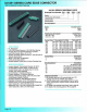


339/389 SERIES CARD EDGE CONNECTOR
.100" (2.
54mm)
Contact Spacing (Bellows Contacts)
CSA
Approved
and
UL
Recognized
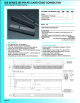
.1
00
(2.54) Contact Spacrng x .200
(5
.08) Row Spactng
Accepts .062
(1
.57) Nominal ThiCkness P.C. Board
High Profile lnsolator Body
•.
600 (15.24)
Contact Tennrnatioo Opt10ns lndude P.C. Tall, Wrre Wrap, 90
Degree & Extender Board Bends
Round
P.C. Tails available
to
fit
.036 (.091) dl!llll8ter holes
Single
or
Dual Row Confrgurations
Large
Variety of Mounting Options, Flush
or
Offset Lugs
Pre·assembled Card Guides Available
Accepts Between
Contae1 and
ln
·Contacl Polarizing Keys
Automatic Wire Wrap Positioning Holes
Insulat
or
Material: Thermoplastic Polyester.
UL
94V..O
Contact Matenal:
Ph
. Bronze
Contact
Platrng: Gold
on
the
Mating Area, Tin·Lead
on
the
Contact Tarls,
NICkel Underplate
Current Ratrng: 3 Amperes Conllnuous
Contact ReSIStance: 10 M
~liohms
Max
imum
Dlelectnc Wrthstand•ng Voltage: 1200 V AC
rrns
at
Sea
Level
Between Adjacent Contacts
Insulation Resistance: 5000 Megohms Mimmum
Operating Temperature:
.05
to
'1'105
Degrees C
Insertion Force: 16
oz
(4.45 N) Maximum per Contact Pair
when Tested with a
,
070
(1.78) Thick Gauge
Withdrawal Force: 1
oz
(0.28 N) Mini
mum
per
Contact Parr
when
Te
sted with a .054 (1.37) Thick Gauge
Page27
Exa
mpl
e Pa
rt
Number
339
- J
oso
-T
520
- 2
02
Ser
i
es
-
-------....1
Total
Number
of
Contac
ts
----.....l
Contact
Code
__________
___J
Contact
Row
s
and
Insulator
Style
------....J
Mounting
Options
---------------'
Series
Insu
l
ator
Colour
339
389
Total
Number
of
Contacts
'
005.006
....
072
01
0,012
... 144
Green
Blacll
Contact Rows
SrngleRow
Dual Row
Contact
Code
u
Descr
i
ption
& Tail Size
Tall
Length
"G"
150
(3.
81
)
186 (4.72)
376 (9.55)
.539 (13.69)
556 (14
t2
)
521
P.C. Tail .025 Square (0.64 Square)
523
P.C. Tall .025 Square
(0
.64 Square)
524
P.
C.
Tarl .025 Square (0.64 Square)
540 Wire Wrap .025 Square (0.64 Square)
541
Wrre Wrap .025 Square (0.64 Square)
556 Extender Board Bend
558 90 Degree Bend
559
90 Degree Bend
560 Extender Board Bend
Contact
Rows
and
Insulator
Style
Descr
i
ption
1 Srngle Row, Flush Mountrng Lugs
2 Dual Row, Flush Mounllng Lugs
4
S•ngle Row,
11
0 (2, 79) Offset Lugs
5 Dual Row
,.
110 (2.79) Offset Lugs
6
Single Row, • t
70
(4.32) Offset Lugs
8 Dual Row,
.
170
(4.32) Offset Lugs
Mounting
Options
•
.•
01
02
03
04
07
08
12
58
78
88
Ordering
Code
Notes
Descript
ion
No
Mounti
ng
Lugs
.128 (3.25) Dia. Mountrng
Holes
116
(2
.95) I
.D
. Floatrng Eyelets
.156 (3.
96
)
D•a
Moun11ng
Holes
M3..o
.5 Metnc Threaded Inserts
114-40
Unrfred Threaded Inserts
128
(3.
25
) Ola. Side Mounting Holes
.468 (11 .
89)
Offset Card Guides
In-line Card
Gu1des
2.750 (
69
.
85
) Long
ln-Une
Card Guides 1
250
(31
75) Long
1) All connector sizes
up
to
72
contacts single row /
144
contacts dual row are available upon request.
2)
For details of
the
extender board and 90 degree bends. refer
to page 61.
3}
For
Jugiess connectors,
code
01
mountrng, spec1fy contact
row
codes 1
or
2
4)
For
detarls
of
t
he
mounting options. refer to page
63
.
-