
Datasheet
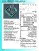


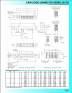

337/387 SERIES CARD EDGE CONNECTOR
.156" (3.96mm) Contact Spacing
CSA Approved and UL Recognized
.156 (3.96) Contact
Spacing x .200
(5
.08) Row Spacing
Accepts .062 (1.57) Nominal Thickness P.C. Board
High Profile Insulator Body,
.600 (15.24)
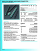
Contact Termination
Options
indude
P.C. Tail, Wire Hole,
Wlre
Wrap,
90
Degree
&
Exte
nd
er
Board
Bends
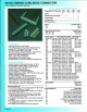
Single
or
Dual Row Configurations
Large
Variety
of
Mounting Options, Flush
or
Offset Lugs
Pre-assembled Card Guides Available
Accepts Between Contact and In-Contact Polarizing Keys
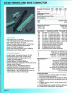
Insulator Material: Thermoplastic Polyest
er
, UL
94V-O
Contact Material: Copper, Nickel, Tin Alloy CA-725
Co
ntact Plating: Gold on the Mating Area, Tin on the
Contact Tails, Nick
el
Underplate
Current Rating: 3 Amperes Continuous
Contact Resistance:
10 Milliohms Maximum
Dielectric Withstanding Voltage: 1800 V AC rms at Sea Level
Between Adjacent Contacts
Insulation Resistance:
5000 Megohms Minimum
Operating Temperature: -65 to +105 Degrees C
Insertion Foroe: 16
oz
(4.
45
N)
Maximum
per
Contact Pair
when Tested with a
.070
(1
.78) Thiok Gauge
Withdrawal Force: 1
oz
(028
N) Minimum per
Co
ntact Pair
when Tested with a
.054 (1.37) Th
lc
k Gauge
Page
37
:
::e
:p
le
Pa
rt
Numb
er T -T · J5
24
· 2 04
T
ota
.l
Nu
mber
of
Contacts
--
---
-'
_
Contact
Code
------
---
---'
Contact
Rows
and
In
sulator
Style
------
---'
M
ou
nt
i
ng
Op
tions
--------
----
--'
Se
r
ies
337
387
I
nsulator
Colour
Green
Black
Total
Number
of
Contacts
1
006
, 007
,.
..
043
C
ontac
t
Rows
Single Row
Dual Row
012
, 014, .•. 086
Contact
Code
>.'
Description
&
Tail
Size Tail
Length
"G"
500
Wire Hole .050 x .
025
(1
.27 x 0.64) .260 (6.60)
520
P.C. Tail .030 x .018 (0
.7
6 x 0.46)
.175
(4.45)
521
P.C. Tall .
025
Square (0.64 Square) .150 (3.81)
523
P.C. Ta
il
.
025
Square (0.64 Square)
.3
90
(9.91)
524
P.C. Tall .018 Square (0.46 Square) .
175
(4.45)
540
Wire Wrap .
025
Square (0.64 Square) .560(14.22)
541
Wir
e Wrap .025 Square (0.64 Square) .750(19.
05)
542
Wire Wrap .
025
Square (0.64 Squar
e)
.645(16.38)
544
Wire Wrap .050 X .025 (1.27 X 0.64) .750(19.05)
555
Extender Board Bend (Code 500 Contacts)
556
Extender Board Bend (
Code
520 Contacts)
558
90
Degree Bend
(Cod
e 541 Con
ta
cts)
559
90 Degree Bend (Code 541 Contacts)
560
Extender Board Bend (Code 523 Contacts)
Contact
Rows
and
Ins
ula
t
or
Style
Description
1 Single Row, Flush Mounting Lugs
2 Dual Row, Flush Mounting Lugs
6
Single Row, .170 (4.32) Offset Lugs
8 Dual Row
..
170 (4.32) Offset Lugs
Mo
unting
Optio
ns •.u
01
02
03
04
07
08
12
58
68
78
Orde
ri
ng
Co
de
Notes
Descrip
tion
No Mounting Lu
gs
.128 (3.25) Oia. Mounting Holes
.116 (2.95) I.D. Floating Eyelets
.
156
(3.
96
) Dia. Mounting Holes
M3-0.5 Metric Threaded Inserts
#4-40
Unified Threaded Inserts
.
128
(3.25) Dia. Side
Mo
unting Holes
.468 (
11
.89) Offset Card Guides
.344 (8. 7
4)
Offset Card Guides
In-Line
Card Guides
1)
All connector sizes
up
to 43 contacts single
row
/86
cortacts
dual row are
ava
il
able upon request.
2)
The
500 contact oode
is
standard in the 337 series only. Green
polyphenylene sulphi
de
Insulator material will
be
supplied.
3)
For details
of
the extender board and 90 degree bends, ref
er
to page 61.
4) For lugless
connectors, oode 01 mounting, specify contact
row
oodes 1
or
2.
5)
In-line card guides are only available
with
offset mounting lugs.
6)
For details
of
the mounting options, refer to page 63.