
Datasheet


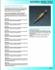

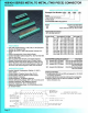


408/424 SERIES METAL TO METAL (TWO PIECE) CONNECTOR
Receptacle
.200 (5.08) Contact Spacing x .125 (3.18) or .150 (3.81) Row
Spacing with Staggered Grid
Accepts
.062 ( 1.57) or ,093
(2
.36) Nominal Thickness P.C.
Board
Edacon Hermaphroditic Contact Mating Design
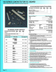
Contact Termination
Options indude P.C. Tail, Fork Tall, Wire
Hole and Wire Wrap
Open
or
Closed Card Slot Ends, Card Guides Optional
Accepts Polarizing Keys without Loss
of
Contact Position
408 Series without Card Guides Designed
to
Mate with
421
Series, 408 Series with Card Guides Designed to Mate
with
422 Series, 424 Series Designed to Mate with 423 Series
Insulator
Material: Polyphenylene Sulphi
de
, UL
94V..O
.
Colour: Green
Contact Material: Phosphor Bronze Alloy
CA-510
Contact Plating: Goid over Nickel for Entire Contact
Current Rating:
10
Amperes
Contact Resistance:
10 Milliohms Maximum
Dielectric Withstanding Voltage:
2000 V AC
rms
at Sea Level
Insulation Resistance: 5000 Megohms Minimum
Operating Temperature:
-65
to
+125 Degrees C
Insertion
and Withdrawal Force:
2to
16 oz
(0
.56 to 4.45 N)
per Contact Position
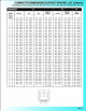
Example Pa
rt
Number 424 -
041
- 500 - 112
Se
ri
es
T T
Total Number
of
Contacts
-----'
Contact Code -
Card
Slot
Width & Mounting Optio
ns
--------'
Series
408
424
Insulator Card Slot Ends
Closed Card
Slot Ends
Open Card Slot Ends per MIL-C-21097
Total Number
of
Contacts
017,023,029
, 035,041
Contact Code
1
·
2
Description & T
ail
Size Tail Length
"G"
500
Wire Hole . 115 x .025 (2.92 x 0.64) .326
(8
.28)
502
Fork Tail .
115
x .025 (2.
92
x 0.64) . 168 (4.27)
520
P
.C.Tai
l .
044x
.
025(1.12x0.64)
.123 (3.12)
521
P,C.Tail .
044x.025(1.12x0.64)
.154 (3.91)
522
P.C. Tail .044 x .025(1.1
2x0.64)
.186
(4
.72)
523
P.C. Tail .044 X .025 (1.
12
X 0.64) .123 (3.12)
524
P.
C.
Tail .
044x.025(1
.
12x0
.64) .154
(3
.91)
525
P.C.
Tail .044 x .025 (1.12 x 0.64) .186 (4.72)
540
Wire Wrap .060 x .025 (1.52 x 0.64) .744(18.90)
541 Wire Wrap
,060 X .025 (1.52 X 0.64) .744(18.90)
542
Wi
re
Wrap .060 x .025
(1
.
52
x 0.64) .965(24.51)
Card
Slot
Width
and Mounting Options
3
Descrip
tion
112 Accepts
.062
(1.57)
Board .
128
(3.25)
Di
a.
Mounting
Holes
122
Accepts
.093
(2.36)
Board
.
128
(3
.25)
Dia
.
Mounting
Holes
212
Accepts
.
062
(1.57)
Board
.
128
(3
.25)
Dia
.
Mounting
Holes
With
Card Guides
222
Accepts
.093
(2.36)
Board
.128
(3.25)
Dia.
Mounting
Holes
With Card Guides
Ordering Code
Not
es
1) Contact codes 523,
524
and 525 are designed for .150 (3.81}
row spacing connectors.
2) Contact
code
540
has a
wire
hole
at
the
tip
of
the
tail
(page
69).
3) Mount
in
g options 212 and 222 are available on the 408
series connectors only.
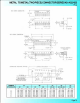
"8"
~
O»
(l.Jl)
0"
I$!
oa&
<o
1o
J
o~
I
I r .
.. .. ..
'-fOR
1<1.
• • c
fNl
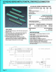
S
CONNECTOR
MOUN
TING
PATTERNS
F'OR
40B
&
424
SERIES
'""t"''l
.+_
e
_e_e_"~-~-e-
+
fOR
COrll.Cf-'
CODES
S2J.,
524
.&
5>75,
J " E • I
IJ6
{J
-'~
)
OlA
-O.S.)
(I
~) &
08
CJ;[Q(S
100
~2
.
,..)
424
5CR£S
.126
(J.I7)
fOR CONl#:T .J
COr.t!t
~20.
!S.a-1
&;
!»21.
Page77