EDAN INSTRUMENTS, INC. Manual Ver: V1.0 Release Date: Aug. 2008 Part Number: MS1R-109455-V1.
Copyright EDAN INSTRUMENTS INC. 2008 Statement EDAN INSTRUMENTS INC. (hereinafter called EDAN) owns all rights to this unpublished work and intends to maintain this work as confidential. EDAN may also seek to maintain this work as an unpublished copyright. This publication is to be used solely for the purposes of reference, operation, maintenance, or repair of our equipment. No part of this work can be disseminated for other purposes.
Using This Label Guide This guide is designed to give key concepts on safety precautions. WARNING A WARNING label advises against certain actions or situations that could result in personal injury or death. CAUTION A CAUTION label advises against actions or situations that could damage equipment, produce inaccurate data, or invalidate a procedure. NOTE: A NOTE provides useful information regarding a function or procedure.
Table of Contents 1 Introduction................................................................................................................. 1 1.1 General Information................................................................................................ 1 1.2 Screen Display ....................................................................................................... 2 1.3 Button Functions.................................................................................................
4 Test and Calculation................................................................................................. 25 4.1 Check the Monitor ............................................................................................. 25 4.2 CO2 Calibration ................................................................................................. 25 5 Disassembly Graph .................................................................................................. 27 5.1 Disassembly Graph.
M3B Vital Signs Monitor Service Manual 1 Introduction ■ ■ ■ ■ ■ General Information Screen Display Button Functions Interfaces Built-in Chargeable Battery 1.1 General Information M3B Vital Signs Monitor (hereinafter called monitor) monitors parameters such as CO2 and SpO2, and is adaptable to adult, pediatric, and neonatal in a hospital environment and during patient transport both inside and outside hospitals.
M3B Vital Signs Monitor Service Manual M3B Vital Signs Monitor can monitor: SpO2: Arterial oxygen saturation (SpO2); Pulse Rate (PR); SpO2 PLETH (Plethysmogram); CO2: End Tidal CO2 (EtCO2); Inspired Minimum CO2 (InsCO2); Air Way Respiration Rate (AwRR). M3B monitor provides extensive functions as visual and audible alarm, net connection, nurse call, recorder and storage for trend data, SpO2/CO2 measurements review, net connection, nurse call, alarm events and so on.
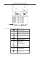
M3B Vital Signs Monitor Service Manual ② Figure 1-3 Main display with data The icons on the interface and their meanings are as follows: Battery status indicator Connected to mains power supply Network connection indicator Network connection off Medium/Low alarm icon High alarm icon Audio system off icon Audio alarm paused icon Parameter alarm off Patient type: ADU -3-
M3B Vital Signs Monitor Service Manual Patient type: PED Patient type: NEO Heart beat ID 08:55:35 Current patient ID Current time Information Area (① ④) The Information area is at the bottom and right part of the screen, displaying operating state of the monitor and status of the patient.
M3B Vital Signs Monitor Service Manual Refer to relative content of parameter for Alarm information and prompt. Charge Indicator and Charge Status To indicate the status of charging: When the battery is charging, the light turns to yellow; after the charge is finished, the light will be off. 1.3 Button Functions ⑤ ⑥ ⑦ ⑧ ⑨ ① ② ③ ④ Figure1-4 Buttons All the operations to the monitor can be finished by several buttons. ① ON/OFF When the monitor is off, press this button to turn on it.
M3B Vital Signs Monitor Service Manual ② SILENCE Press this button for less than 2s to pause audio alarm for 2min, then the icon displays. When repress it or the pause time is over, the audio alarm can resume to the normal monitoring status. Press this button for more than 2s can turn off the audio system, including audio alarm, key volume and pulse tone. displays in Information area. Press the The icon button again can resume the audio system. CO2 START/STOP Press to start the CO2 measuring.
M3B Vital Signs Monitor Service Manual monitor. Left Side of the Monitor At the left side of the monitor, there is the recorder’s paper inlet cover (①). ① ② ③ Figure1-5 Left Panel Sensor port on the front panel Connectors for cables and sensors are as shown in Figure 1-5. 1. SpO2 sensor connector ② 2. CO2 sensor connector ③ WARNING Only connect the device to EDAN supplied or recommended accessories. Rear Panel ! This symbol means “BE CAREFUL". Refer to the manual.
M3B Vital Signs Monitor Service Manual This symbol indicates that the instrument is IEC/EN60601-1 Type BF equipment. The unit displaying this symbol contains an F-Type isolated (floating) patient applied part providing a high degree of protection against shock, and is suitable for use during defibrillation. ① ③ ② Figure1-6 Rear Panel of M3 Sockets on the rear panel are shown in Figure1-6, ① Equipotential grounding terminal for connection with the hospital’s grounding system.
M3B Vital Signs Monitor Service Manual Battery compartment cover Fuse box Figure1-7 Bottom panel 1.5 Built-in Rechargeable Battery The monitor is equipped with a built-in rechargeable lithium-ion battery (hereinafter called battery). When switch on AC power supply, the battery will be recharged automatically until full electric energy. There is a sign “ ” or “ ” in the lower right corner of screen.
M3B Vital Signs Monitor Service Manual For recharging, the battery is 90% to 100% charged after 5 hours of recharging. Replace Battery During monitoring state or communication state, when the electric energy of battery is low or empty, the battery state icon will display and flash. When the lifespan of battery is over, or foul odor and leakage has been detected, please contact with manufacturer or local distributor for replacement of battery. WARNING Do not take off the battery when monitoring.
M3B Vital Signs Monitor Service Manual disassemble or modify the battery. WARNING Before transporting, the battery should be taken off from monitor. WARNING Please take out the battery before storing the monitor for more than 1 month.
M3B Vital Signs Monitor Service Manual 2 Principle 2.1 General Parts The monitor has been designed to measure physiological parameters including SpO2 and CO2. There are five parts in monitor, see figure 2-1. • Parameter measuring part • Main control part • Interface part • Power supply part • Other auxiliary parts Interface part Main control Power supply part part Parameter measuring part Other auxiliary parts Figure2-1 Monitor Structure 2.1.
M3B Vital Signs Monitor Service Manual 2.1.2 Main Control Part Main control board consists of Core board and Interface board. It has CPU/memory, display circuit, network circuit and I/O interface. Main control board of the integrated board is used to drive man-machine interface, manage parameter measurement and provide other specific functions to the user such as configuration storage, waveform and data review, etc. 2.1.
M3B Vital Signs Monitor Service Manual Speaker Battery Alarm board Fan Power module Keyboard Slave keyboard Power control board RJ45 Port LCD backlight LCD data 2410 Main control board SpO2 module SpO2 sensor CO2 module CO2 sensor USB board Wireless module Network board Nurse call Recorder Figure2-2 Structure and Part Relationship NOTE: The Nurse call board and the Network board are optional configuration, they can not be installed at the same time.
M3B Vital Signs Monitor Service Manual Battery Fan Power board Power control board Figure2-3 Schematic Diagram of Power Board Principle Introduction This module converts 220V AC mains power supply or battery power into 5V, 12V and -12V DC supplies to power other boards. If AC mains and battery coexist, the former take the priority to power the system and charge the latter at the same time.
M3B Vital Signs Monitor Service Manual Voltage Detection Circuit Detects the output voltage of every part in detection circuit, converts analogue signals to digital signals and then send them to Main control board for processing. 2.2.
M3B Vital Signs Monitor Service Manual RTC RTC can offer second, minute, hour, day, month, year and other calendar information. CPU can gain such calendar information from RTC, it also can rewrite the data in RTC. Ethernet Controller Ethernet controller supports IEEE 802.3/IEEE 802.3u Ethernet standard, supports 10Mbpsdata transmission rate. CPU exchanges data with Ethernet via Ethernet controller. LCD Controller LCD controller can control LCD display. 2.2.
M3B Vital Signs Monitor Service Manual Principle Introduction This module detects key and encoder input signals, converts them into codes and sends to Main control board. Main control board sends command to the keyboard and the latter accordingly control indicator and audio process circuit to realize audio and visual alarm. CPU Detect key and encoder input signals; Control LED status; Regularly zero Watchdog Timer; Communicate with Main control board.
M3B Vital Signs Monitor Service Manual data into dot matrix data and sending them to the thermal recorder, it also drives the recorder to start printing action. Step Motor Drive Circuit A step motor is used in the recorder to feed paper. This circuit is designed to drive the step motor. Recorder Status Detect Circuit Detect the status of the recorder and send the information to CPU System, including the position of paper platen, whether there is paper, temperature of thermal head.
M3B Vital Signs Monitor Service Manual It indicates software system inner the frame above, on the left of frame is software system input, and on right is software system output; parameter measuring module exchanges data with software system by serial ports, while user communicates with system by keyboard; among the output devices, recorder and alarm devices receive data via serial ports, the analogue output apparatus is MBUS, screen and network controller are controlled directly by CPU. 2.3.
M3B Vital Signs Monitor Service Manual 2.4 System Parameters 2.4.1 General Parameter module is the basic unit to acquire signals for monitoring parameters in monitor. The results are transmitted to Main control board by keyset to finally accomplish processing and displaying of data and waveforms. Main control board commends and module status messages can also be transmitted via keyset. The keyset can also realize power switching and conversion.
M3B Vital Signs Monitor Service Manual 2.4.2 SpO2 SpO2 is based on the absorption of pulse blood oxygen to red and infrared light by means of finger sensor and SpO2 measuring unit. The light-electronic transducer in finger sensor converts the pulse red and infrared light modulated by pulse blood oxygen into electrical signal, the signal is processed by hardware and software of the unit. The PLETH curve and numeral value of SpO2 will be obtained.
M3B Vital Signs Monitor Service Manual 3 Installation of Monitor 3.1 Open the Package and Check Open the package and take out the monitor and accessories carefully. Keep the package for possible future transportation or storage. Check the components according to the packing list. n Check for any mechanical damage. n Check all the cables, modules and accessories. If there is any problem, contact the manufacturer or local representative immediately. 3.
M3B Vital Signs Monitor Service Manual 3.4 Connect Sensor to Patient Connect all the necessary patient sensors between the monitor and the patient. NOTE: For information on correct connection, refer to related chapters in User manual. 3.5 Check the Recorder If your monitor is equipped with a recorder, open the recorder door to check if paper is properly installed in the slot. If no paper present, refer to User manual for details. 3.
M3B Vital Signs Monitor Service Manual 4 Test and Calculation 4.1 Check the Monitor For the conventional testing contents of monitor, please refer to the User Manual. The information in this chapter is only a brief introduction. First check the device appearance and installation, and be sure that: 1) The shell of the device is clean and has no scratches. The installation is stable. When shaking the device, these is no inside leftovers. 2) Buttons are smooth and free for operation.
M3B Vital Signs Monitor Service Manual for CO2 monitoring function. Before you using the CO2 module, you can do zero calibration by ZERO CAL in CO2 SETUP. Zero Calibration: Enter SYSTEM MENU → CO2 SETUP, the menu displays: Figure4-3 CO2 Gain Calibration ZERO CAL: used to perform zero calibration for CO2 module.
M3B Vital Signs Monitor Service Manual 5 Disassembly Graph This chapter introduces the inner structure and parts of the monitor, including disassembly graph, front shuck assembly, rear shuck assembly and main bracket assembly. 5.1 Disassembly Graph 6 1 7 2 3 4 5 1: M3 Front shuck assembly; 2: Main bracket assembly; 3: M3 rear shuck assembly; 4: Cross recessed countersunk head screw M3×6; 5, 7: Cross recessed round head screw M3×25; 6: Cross recessed pan head coil spring screw.
M3B Vital Signs Monitor Service Manual 29 19 14 15 16 24 25 27 21 22 23 26 20 17 18 30 28 31 32 33 34 1 2 3 4 5 6 7 8 9 12 11 13 10 1, 7: Cross recessed pan head screw M3×6; 2: Main control board; 3: M3 Main control board Insulated gasket; 4: M3 Screen bracket; 5, 8, 21, 26: Cross recessed pan head self-tapping screw ST3×8; 6: 5.
M3B Vital Signs Monitor Service Manual 5.3 Rear Shuck Assembly 10 8 11 9 12 7 6 5 13 4 14 15 3 16 17 2 1 1: M3 rear shuck rubber feet; 2: M3 battery compartment cover; 3: M3 recorder slot cover; 4, 9: Cross recessed pan head self-tapping screw ST3×8; 5: M3 recorder bracket; 6: M3 Rear shuck; 7: Cross recessed pan head self-tapping screw ST2.
M3B Vital Signs Monitor Service Manual 5.
M3B Vital Signs Monitor Service Manual 6 Troubleshooting In transportation, storage and use of monitor, various factors such as unstable network voltage, changing environmental temperature, falling-down or impact, component aging may all result in monitor failures and therefore affect normal application of the device.
M3B Vital Signs Monitor Service Manual ③ Poor performance of ③ Replace Main control board Main control board ④ Bad connection of ④ Replace power supply or Main connectors control board or repair 6.2 Display Failures Failure Possible cause When powering on the device, power supply is in normal operation, however, there is no display or screen goes black during normal operation.
M3B Vital Signs Monitor Service Manual Record paper goes out ① Bad recorder installing or ① Adjust the installation skewwhiffly. positioning. of recorder. ① Network linking wire is ① Check and repair damaged. network linking wire or HUB. Can not be linked into ② Network bed No. conflicts network ③ Main control board failure ② Change bed No. ③ Replace Main control board 6.4 Power Board Failures Possible cause Failure Solution ① Short-circuit occurs in ① Check after power on power supply or other part.
M3B Vital Signs Monitor Service Manual No CO2 waveform ① Poor connection of the ① Turn off the monitor and CO2 module reconnect the CO2 module ② The damaged CO2 module is ② Replace the CO2 module The CO2 waveform is ① The CO2 module is at ① Change the STANDBY mode a beeline STANDBY mode to MEASURE mode ② The sample line is blocked ② Draw off the sample line, clear or disconnected it or replace it to another one.
M3B Vital Signs Monitor Service Manual 7 Maintenance and Cleaning 7.1 General Cleaning WARNING Turn off the power and disconnect the line power before cleaning the monitor or the sensor/probe. CAUTION Pay special attention to avoid damaging the monitor: 1) Avoid using ammonia-based or acetone-based cleaners such as acetone. 2) Most cleaning agents must be diluted before use. Dilute the cleaning agent as the manufacturer's direction. 3) Do not use the grinding material, such as steel wool, etc.
M3B Vital Signs Monitor Service Manual c. Hydrogen Peroxide 3% d. Alcohol e. Isopropanol ■ Sterilization To avoid extended damage to the equipment, sterilization is only recommended when stipulated as necessary in the Hospital Maintenance Schedule. Sterilization facilities should be cleaned first.
M3B Vital Signs Monitor Service Manual For cleaning C5 CO2 module or LoFlo CO2 module: 1. Use a cloth dampened with isopropyl alcohol 70%, a 10% aqueous solution of sodium hypochlorite (bleach), disinfectant spray cleaner such as mild soap. 2. Wipe down with a clean water-dampened cloth to rinse and dry before use. Make certain that the sensor windows are clean and dry before reuse. 7.
M3B Vital Signs Monitor Service Manual ITALIAN, GERMAN, RUSSIAN, POLISH, FRENCH or SPANISH. NOTE: Please restart the monitor after changing the language. n ALM SOUND: You can set alarm sound to ON or OFF. For more details refer to Chapter Alarm. n NURSE CALL: turn on or off the nurse call. When the parameter alarm occurs, the monitor gives 3s nurse call alarm prompt; if the audio alarm or the audio system is off, the monitor can also give the nurse call alarm in abnormal condition. n EXIT: exit the menu.
M3B Vital Signs Monitor Service Manual 8 Accessories and Ordering Information WARNING The specification of accessories recommended is listed below. Using other accessories may damage the monitor. The following accessories are recommended when using this monitor. Part No.
M3B Vital Signs Monitor Service Manual M50-078155 Adult Airway Adapter/MainStream 6063 M50-078156 Infant Airway Adapter/MainStream 6312 M50R-78035 Printing Paper MS3-30493 Mounting system (Simple) MS3-30164 Mounting system M21R-064115 Rechargeable Lithium-Ion Battery/HYLB-1049 (14.8V, 4.
M3B Vital Signs Monitor Service Manual 9 Warranty and Service Standard Service The warranty period begins on the date the products are shipped to customers. If customer promptly notifies EDAN of customer’s warranty claim hereunder, EDAN will either repair, adjust or replace (with new or exchange replacement parts) the EDAN’s product. EDAN warrants that any service it provides to customers will be performed by trained individuals in a workmanlike manner.
M3B Vital Signs Monitor Service Manual EDAN on time. We will, at this option, dispatch the replace one(s) with confirmed shipping invoice. NOTE: (1) Both Return Material Authorization Form and Declaration Form are offered by EDAN service department once the SCF is confirmed by service engineer. (2) Customer is responsible for freight & insurance charges when the equipment is shipped to EDAN for service including custom charges.
M3B Vital Signs Monitor Service Manual Contact Information If you have any question about maintenance, technical specifications or malfunctions of devices, do not hesitate to contact us. EDAN Instruments, Inc. TEL: +86-755-26898321, 26899221 FAX: +86-755-26882223, 26898330 E-mail: support@edan.com.
M3B Vital Signs Monitor Service Manual AppendixⅠProduct Specification A1.1 Classification Anti-electroshock type ClassⅠequipment and internal powered equipment EMC type Anti-electroshock degree Ingress Protection Working system Class A SpO2, CO2 BF Defibrillation type IPX1 Continuous running equipment (less than 7 days) A1.2 Specifications A1.2.1 Size and Weight Size Weight 173.5 (L) × 241 (H) × 189 (D) mm 3kg A1.2.
M3B Vital Signs Monitor Service Manual 1 Power On Indicator LED (Green) 1 Alarm Indicator LED (Orange/ Red) 1 Charge Indicator LED (Yellow) 1 Alarm Sound Indicator LED (Backlight) 1 CO2 Working Status Indicator LED (Backlight) 3 Sound Modes correspond to Alarm Mode A1.2.4 Battery Quantity Type Power-off delay Voltage Capacitance Working period Rechargeable period 1 Li battery 5 ~ 15min 14.8 VDC 4, 400 mAh >290min(at 25℃,continuous SpO2 measuring mode) < 5 hours A1.2.
M3B Vital Signs Monitor Service Manual Measuring and Alarm Range Resolution 15 ~ 254 bpm 1 bpm Accuracy ± 3bpm Under Motion Condition, ±5 bpm Anti-low-perfusion Anti-motion Interference Strong Anti-low-perfusion, 0.075 ~ 0.
M3B Vital Signs Monitor Service Manual Reading ±10%, 77 ~ 99 mmHg AwRR Alarm range CO2 InsCO2 AwRR ±2 rpm ADU PED NEO ALM HI ADU PED NEO 15 ~ 50 mmHg 20 ~ 50 mmHg 30 ~ 45 mmHg 4 mmHg 8 ~ 30 rpm 8 ~ 30 rpm 30 ~ 100 rpm Suffocation Alarm Delay AwRR Response time Calculation Method 10 ~ 40 seconds <3 seconds, includes transport time, risetime BTPS (Body Temperature Pressure Saturated) Stability Short Term Drift Long Term Drift <0.
EDAN INSTRUMENTS, INC. Addr: 3/F-B, Nanshan Medical Equipments Park, Nanhai Rd 1019#, shekou, Nanshan Shenzhen, 518067 P.R.