
Product Manual


M3B Vital Signs Monitor Service Manual
- 28 -
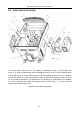
1, 7: Cross recessed pan head screw M3×6; 2: Main control board; 3: M3 Main control
board Insulated gasket; 4: M3 Screen bracket; 5, 8, 21, 26: Cross recessed pan head
self-tapping screw ST3×8; 6: 5.7 inches LCD; 9: Main control keyboard; 10: M3 Main
control keyboard pressure plate; 11: M3 Main control keyboard silica gel button; 12, 13:
M14 hexagon head nut; 14: Cross recessed pan head self-tapping screw ST3×15 plain;
15: Cross recessed pan head screw M3×4 (iron); 16: M3 alarm light fixed board; 17:
Alarm light board; 18: Cross recessed pan head screw M2×3; 19: M3 short sponge bar
91.6×9×2.5; 20: M3 long sponge bar 136×9×2.5; 22: Insulated plain washer Φ10.3MM
(red); 23: Slave keyboard; 24: M3 slave keyboard pressure plate; 25: M3 slave keyboard
silica gel button; 27: M3 copper grounding sets; 28: USB board; 29: M3 USB silica gel
seal cover; 30: M3 alarm lampshade; 31:5.7 inches LCD screen protection/Homochromy;
32: CO
2
connector; 33: SpO
2
connector; 34: M3 front shuck and seal Φ2.0×160MM.
Figure5-2 Front shuck assembly
14
15
16
17
18
19
20
21
22
23
24
25
26
27
28
29
30
31
32
1
2
3
4
5
6
7
8
9
10
11
12
13
33
34