E-CPU12-I-0113 Operator’s Instruction Manual Model CPU-12 Self-Propelled Concrete/Asphalt Planer 100 Thomas Johnson Drive, Frederick, MD 21702-4600 USA Phone (301) 663-1600 • 1-800-638-3326 Fax (301) 663-1607 • 1-800-447-3326 Website: www.edcoinc.com Email: sales@edcoinc.
E-CPU12-I-0113 READ AND UNDERSTAND THE OPERATORS INSTRUCTION MANUAL THOROUGHLY BEFORE ATTEMPTING TO OPERATE THIS EQUIPMENT. Death or serious injury could occur if this machine is used improperly. SAFETY SAFETY MESSAGES MESSAGES • Safety Instructions are proceeded by a graphic alert symbol of DANGER, WARNING, or CAUTION. Indicates an imminent hazard which, if not avoided, will result in death or serious injury. Indicates an imminent hazard which, if not avoided, can result in death or serious injury.
E-CPU12-I-0113 Equipment Instruction Manual EDCO Model CPU-12 Table of Contents Section Page Number Safety Guidelines....................................................................................................4 Operating Instructions.............................................................................................5 Maintenance............................................................................................................8 Inspect & Tension Belts.............................
E-CPU12-I-0113 Read and understand the Operator’s Manual, and the Engine Manufacturer’s Owner’s Manual before operating this equipment. Death or serious injury can result if this machine is used improperly. Safety Guidelines Maintain a safe operating distance from flammable materials. Sparks from the cutting-action of this machine can ignite flammable materials or vapors. Operator must wear appropriate clothing and footwear.
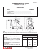
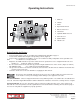
E-CPU12-I-0113 Operating Instructions 1. Ammeter 3 2 2. Throttle 4 1 5 4. Depth Control Knob 9 6 5. Drive Control Lever 8 10 3. Choke 7 6. Hour Meter 10 7. Hydraulic Drum Lift Lever 8. Cam Lift Lever 9. Ignition Switch 10. Handle Lock Figure 2 Before Starting the Engine: • Inspect machine before each use according to the Maintenance Schedule on page 11. • Locate and be familiar with all engine and operating controls (Figure 2). • Inspect cutters carefully before installing.
E-CPU12-I-0113 Starting the Engine/Motor and Controlling the Cut: • • • • - Be sure drum is clear of the ground. Start the engine according to the manufacturer’s instructions. For electric models, depress “On” switch. Engine must be at FULL THROTTLE. Slowly lower the cutter head to the slab surface with the hydraulic drum lift lever. Lift the depth control handwheel knob to unlock and turn to the handwheel until the cutter head reaches the desired depth.
E-CPU12-I-0113 Additional Information: • Since cutter wheels wear, the cutting depth will change. Compensate for wear by adjusting the depth control. To reach greater depth in the concrete it is best to make several passes at increments of 1/8” to 3/16” per pass. Never use a fine spaced cutter head to cut deeper than 1/8”. All deep cuts should be started from a stationary position. When the cutting depth is reached the plane should then move forward.
E-CPU12-I-0113 Remove all rings, watches and jewelry prior to doing maintenance near the hydraulic pump. Maintenance Refer to the engine manual for maintenance information specific to the engine used. Disconnect the machine from the power source. Remove the spark plug lead on the gasoline engine models or disconnect the supply voltage connector on the electric models, before performing any maintenance. All maintenance should be performed regularly by qualified personnel.
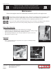
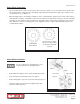
E-CPU12-I-0113 Cutter Wheel Inspection: • The steel cutter wheels can be used as long as the teeth can be clearly seen on each cutter wheel and the cutter wheel edge must be clearly above the drum flange edge when pushed towards the drum center. Replace worn out cutter wheels as a complete set. • When changing cutters, check drum assembly for cracks or other damage. Replace bent or worn cutter shafts or cracked drum assemblies. A maximum of 30% wear on shafts before they must be replaced.
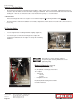
E-CPU12-I-0113 Inspect & Tension Belts: • Proper belt tension must be maintained to transmit the engine power to the cutter drum. Slipping belts will over heat, the cutter life will be shortened and the cutting speed limited. Over tensioned belts will shorten the belt and bearing life. 70 ft. lbs. of deflection at the center between the pulley’s, is recommended. !! IMPORTANT!! After tensioning belts make sure engine is level and then tighten all mounting hardware and jam nuts.
E-CPU12-I-0113 Repairs are to be done by authorized EDCO DEALERS only.
E-CPU12-I-0113 LIMITED EQUIPMENT WARRANTY OF SALE – TERMS & CONDITIONS Equipment Development Company, Inc. herein referred to as EDCO (Seller) warrants that each new unit manufactured by EDCO to be free from defects in material and workmanship in normal use and service for a period of (90) ninety days (except for the cutter drum assembly on all model concrete/asphalt planes, in which case the warranty period shall be 90 days) from date of shipment to the original retail or equipment rental center owner.