
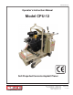
User Manual

E-CPU12-I-0113
Printed in USA
©2013
TVW
Page 6
100 Thomas Johnson Drive, Frederick, MD 21702-4600 USA
Phone (301) 663-1600 • 1-800-638-3326
Fax (301) 663-1607 • 1-800-447-3326
Website: www.edcoinc.com
Email: sales@edcoinc.com
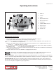
Starting the Engine/Motor and Controlling the Cut:
•
Be sure drum is clear of the ground.
• Start the engine according to the manufacturer’s instructions. For electric models, depress “On” switch.
• Engine must be at FULL THROTTLE.
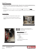
• Slowly lower the cutter head to the slab surface with the hydraulic drum lift lever. Lift the depth control handwheel
knob to unlock and turn to the handwheel until the cutter head reaches the desired depth.
- Never plane deeper that the maximum depth of surface removal for the assembly being used. If it
is necessary to remove a deep layer of material, make several shallow passes to achieve desired
depth.
- Only cut in a forward direction.
- Always cut with the engine at full throttle.
NOTE: The engine/motor should not labor. Adjust forward speed to fi t the work being performed. Very hard concrete
will have to be planed at a slower pace then asphalt or deteriorated surfaces. If it is necessary to make deep passes,
make several shallow cuts to achieve the desired depth.
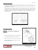
• If front wheels are not in contact with slab surface when planing, you are bottoming the cutter head. You are rid-
ing on the drum & cutter wheels. Cutter wheels will wear uneven or break if this is continued. Readjust depth
- turn fi ne adjustment in “up” direction until cutters are free and cutting is being accomplished by
“hammering” action only.
Failure to follow these instructions will cause undue cutter wear, breakage, bearing failure or exces-
sive vibration that will be transmitted back to the machine frame and engine eventually causing a
virtual self-destruction of the unit.
Controlling Speed:
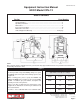
• The CPU-12 uses a hydrostatic transmission and positive chain drive mechanism to power both rear wheels to
achieve forward and reverse movement. Machine speed is controlled by using the speed control lever. The lever
is spring loaded and returns to neutral when released. Actual cutting speed is determined by hardness of the
material and depth of desired removal. Adjust forward speed to meet working conditions.
To Stop Cutting:
• Move drive control lever to neutral.
• Raise cutter head assembly using the hydralic drum lift lever to clear the slab surface.
For Gasoline Models: Close throttle and turn the ignition switch to the “off” position.
For Electric Models: Depress the “off” button.
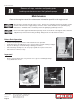
After Operation:
• Clean the entire machine after it has cooled. Check for worn or damaged cutters and perform any required
maintenance. See maintenance instructions.