
Owners manual


Page 12
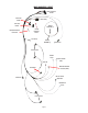
PRO-FLO 3 EFI INSTALLATION
NOTE: Though visually different, the installation procedure is relatively the same between manifolds using 4150 style throttle bodies and XT type
throttle bodies.
1. Disconnect the battery. Drain the radiator coolant (radiator drain plug is typically located on lower right facing engine). WARNING! Do NOT drain
coolant while engine is hot.
2. Remove the gas cap to release any fuel pressure present in the system. Remove the air cleaner, throttle linkage, vacuum and fuel line from the
carburetor. Remove all brackets and the radiator hose (if applicable) from the intake manifold. TIP: Tag all linkages, vacuum and fuel lines. This
will simplify the installation.
3. Rotate the engine to 12° Before Top Dead Center (BTDC) on the compression stroke of cylinder #1.
4. Remove the distributor hold down clamp and remove the distributor from the engine.
5. Clean all debris from the intake manifold and unbolt the carburetor and intake manifold. NOTE: Removal of the valve covers may be required on
some applications. If valve covers are removed, replace the valve cover gaskets as needed.
6. Place rags or paper towels into the cylinder head ports and lifter valley to prevent debris from falling into the ports and combustion chambers.
7. Remove the gaskets and gasket residue using a metal scraper. Vacuum up any debris before proceeding.
8. Remove the rags or paper towels from the cylinder head ports. Using a shop rag and lacquer thinner, clean the head/manifold mating surface.
9. Test fit manifold to cylinder heads to verify fit and that there are no interferences.
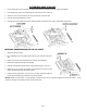
10. Apply two (2) thin layers of Gasgacinch to the head/manifold mating surface (Figure 1) and one (1) side of the supplied intake manifold gaskets
(Figure 2). Let the Gasgacinch tack up for about one (1) minute.
Figure 1
Figure 2
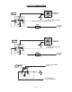
11. Position the intake manifold gaskets (side with Gasgacinch) onto the cylinder heads making sure to align the intake ports. Press down firmly to
secure (Figure 3).
12. Using finger, apply a thin layer of gasket maker around the intake ports and a slightly thicker layer around the water jackets (Figure 4). Do this
for both intake manifold gaskets.
Water Jackets
Intake Ports
Figure 3
Figure 4
13. Apply a bead of gasket maker about a 1/4” thick to the front and rear of the block as shown (Figure 5).