
Corporation Viper Shocks Installation Instructions
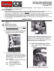


Step 10 Installing IAS shocks
Reinstallation is reverse of removal.
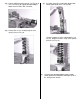
10(a) Both front and rear may require a little gentle
persuasion with a long pry bar to push control
arms down in order to install bolts (see Fig. 22
and Fig. 22a). Do not torque nuts at this time.
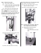
Front lower bolts may be installed with nuts to
the front. This will make it easier for
reassembly.
Fig. 22
Fig. 22a
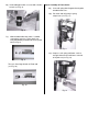
10(b) Front sway bar end links may now be
reinstalled. Install both left and right at the
same time. After both sides are in position, the
end link to control arm nuts can be torqued to
16 ft lbs.
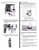
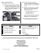
10(c) Important: After all four shocks are installed,
place jack or jack stand under control arm –
support vehicle to load suspension at ride
height and torque bolts to:
Front (upper and lower) 80-100 ft. lbs.
Rear (upper) 80-100 ft. lbs.
Rear (lower) 130 ft. lbs.
This must be done to pre-load bushing for their
proper position in order for safe and proper
handling. This is a very important step.
10(d) Install and torque wheels to 90 ft. lbs. After
5-10 miles, re-torque wheels to 90 ft. lbs.
Parts List
Qty. Description Qty. Description
2 #33505 Front shock assemblies 1 Crowfoot wrench (for removal of shock from clevis)
2 #34505 Rear shock assemblies 1 Spanner wrench (for installing and torquing of rear
2 Rear rodend clevis adapters threaded clevis adapter and jamb nut)
2 Rear rodend clevis adapter locknuts 1 Loctite tube
4 Upper coilover spring perch 1 Anti-seize
4 Coilover threaded sleeves 1
Hardware kit
4 - set screws
4 - 9/16 jam nuts
Enjoy the improved ride and handling from your new Edelbrock IAS shocks.
Edelbrock Corporation
2700 California Street
Torrance, California 90503
Office (310) 781-2222
Fax (310) 320-1187
Toll-Free Tech Line (800) 416-8628
Tech E-mail: edelbrock@edelbrock.com
PN 84-8152
2001 Edelbrock Corporation
Revised 2/01