
Corporation Automobile Parts User Manual

Catalog #3562, 3563, 3564, 3565
Rev. 3/06 Page 9 of 16
©2006 Edelbrock Corporation
Brochure #63-0047
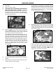
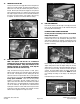
16. HEATER HOSE SUPPLY LINE
For all years, the heater core supply will come from the right front
water port on intake manifold. You will need to install the 1/2"
NPT-to-3/4" hose fitting into manifold using Teflon sealant on
threads. Remove your existing heater supply hose at its junction
point, usually at the heater core. Using the 3/4" heater hose and
two clamps supplied, route the hose from the intake manifold to
the heater core supply entrance. Some cutting of the hose may
be required. Secure hose on both ends with hose clamps.
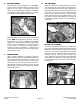
17. INJECTORS AND RAILS
NOTE: Fuel injectors and fuel rails are assembled on
manifold and ready to run unless you had to remove them
for manifold installation. If they were removed, use the
following procedure for re-installation. If not, skip this
procedure and move on to the next step.
Using non-silicone based spray lubricant or white grease,
lubricate injector O-rings (top and bottom) before sliding them
into fuel rails. Push injectors into rails, making sure that the
electrical connectors on injector bodies face up. Now push fuel
rails and injectors into manifold. Use caution not to damage
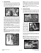
O-rings upon installation. Place fuel rail with pressure
regulator on passenger's side with regulator toward rear of
engine. Place other rail on driver's side of manifold. Push down
with enough force to seat lubricated O-rings in manifold, making
sure not to cut O-rings. Once injectors are seated and before
replacing the 1/4-20 x 1.25 bolts, make sure the injectors rotate
in their bores easily. Once installed, secure rails with 1/4" bolts
and flat washers supplied in kit. Torque to 8 ft./lbs.
18. FUEL LINE CONNECTION
From the kit contents, locate the length of 3/8" high pressure fuel
hose, one 45° #6 Pushlock fitting, one 90° Pushlock fitting, and
two straight #6 Pushlock fittings.
PUSHLOCK FITTING-TO-HOSE INSTALLATION
Use this procedure for installing each one of the Pushlock
Fittings onto hose ends:
Clamp Pushlock fitting in vise, being careful not to crush fitting.
Lubricate inside of hose end and Pushlock fitting barb with a
small amount of lubricant (oil, spray lube, or white grease). Push
the hose over the barb until it stops against the fitting collar. No
clamping is necessary.
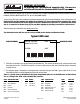
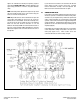
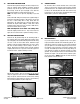
Before making the fuel lines, you must install the fuel filter
adapter fitting and the return line adapter fitting. The fuel filter
adapter fitting is a male #6-to-16mm threaded male with an O-
ring on the end of the fitting. Install into fuel filter and tighten
securely. The return adapter fitting is the female 14mm-to-#6
fitting. This will attach to the return fuel line. NOTE: Be careful
not to damage the O-rings on the fittings or the existing fuel
lines.
Install both fittings as shown in photo.
Return Line Adapter
Fitting (14mm)
Fuel Filter Adapter
Fitting (16mm)