
Corporation Tubular Exhaust System (T.E.S.) Installation Instructions

©2007 Edelbrock Corporation
Catalog #s 68932, 68933, 68942, 68943
Page 2 of 2
Brochure #63-68932
Rev. 7/07 - DA/mc
10. Replace water temperature wire.
11. Replace spark plugs and wires.
12. Re-install A.I.R. fittings (use A.I.R. adapter fitting in kit,
if necessary).
Extension Pipe
1. Cut O.E.M. exhaust pipe approximately 1/2” to 3/4” in
front of the catalytic.
2. Bolt catalytic back into vehicle with front in original
location.
3. Install T.E.S. pipe over catalytic inlet and bolt to T.E.S.
manifold using donut gaskets provided.
4. With everything in place, tack weld T.E.S. to catalytic.
Note: Tig welding is desirable but gas welding can be
used.
5. After tack welding, remove assembly and complete
weld.
6. Re-install assembly and tighten all bolts.
7. Check all wires and lines for adequate clearance.
FINAL INSPECTION
1. Check all hydraulic, vacuum, and fuel lines to ensure
there is adequate clearance to T.E.S. components.
2. Re-connect battery.
3. At this point, it is a good idea to look everything over and
make sure nothing was missed in assembly.
4. Start vehicle and bring up to normal operating
temperature. Check for possible leaks.
5. Turn engine off and let cool. Tighten all bolts again.
12. Re-install spark plugs and wires.
Note: Alternator and dipstick tube must be removed
for future spark plug changes.
13. Re-install alternator and A.I.R. fitting. Use A.I.R.
adapter fitting and kit, if necessary.
14. Re-install dipstick tube.
15. Take wire pack (wrapped with aluminum tape) out of
plastic clip on crossmember and re-position toward
front of vehicle for additional protection from heat.
Use tie wrap (in kit) to secure.
Left Side
1. Remove spark plugs.
2. Unplug temperature sensor wire connector.
3. Remove plastic cover around lower steering shaft.
Steering shaft must be removed for installation of
T.E.S.
4. Remove by unbolting at top of upper universal joint
and bottom of lower universal joint. Slip upper joint
up steering shaft while sliding lower joint off steering
box serrated shaft.
5. Disconnect A.I.R. hose.
6. Remove exhaust manifold.
7. Install T.E.S. flange gasket and one 3/8”-16 x 1” bolt,
lock washer and flat washer at rearmost bolthole
(leave bolt loose enough to accept T.E.S.).
8. Place manifold into position from above. Start all
manifold bolts, and washers, then tighten.
9. Replace steering shaft and plastic cover.
Qty. PN Description
❑ 1 25-9444 Header left side (#68932) (Ceramic)
❑ 1 25-9445 Header right side (#68932) (Ceramic)
❑ 1 25-9070 Header left side (#68933) (Ti-Tech)
❑ 1 25-9071 Header right side (#68933) (Ti-Tech)
❑ 1 25-9337 Header left side (#68942) (Ceramic)
❑ 1 25-9338 Header right side (#68942) (Ceramic)
❑ 1 25-9070 Header left side (#68943) (Ti-Tech)
❑ 1 25-9075 Header right side (#68943) (Ti-Tech)
❑ 1 25-9583 Extension Y-pipe
❑ 2 - Chevy V8 port gaskets
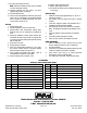
KIT CONTENTS
Catalog #s 68932, 68933, 68942, 68943
Qty. PN Description
❑ 2 - Donut gaskets; 2-1/2”
❑ 4 - Flat washers; 3/8”
❑ 12 - Hex header bolts; 3/8” x 1”
❑ 1 - Spacer tube; 5/8” x 1-1/8” Long
❑ 4 - Hex capscrews; 3/8” x 2”
❑ 1 -
Hex capscrews; 12-point head, 3/8” x
2-1/4”
❑ 16 - Lockwashers; 3/8”
❑ 1 -
Tie Wrap; 11”
❑ 2 - Fittings; A.I.R. adapter
Edelbrock Corporation, 2700 California St., Torrance, CA 90503
Tech Line: 1-800-416-8628
E-Mail: Edelbrock@Edelbrock.com