
Specifications


Catalog #3615, 3616
Rev. 6/07 - RS/mc
©2007 Edelbrock Corporation
Brochure #63-3615Page 4 of 4
Crank Trigger Applications:
In crank trigger applications, the
distributor does not control the ignition timing so adjusting rotor
phasing is easy. Simply rotate the distributor housing until the
rotor tip is in the correct position.
Phasing and Electronic Timing Controls:
When setting the
phasing, you also need to take into consideration any timing
controls or retard controls. If you are advancing or retarding the
timing electronically, you are affecting rotor phasing. In most
cases, the timing change will not be enough to affect the
phasing, but there are certain applications to watch out for. One
such application is engines using multiple stage nitrous systems
and retard steps. High performance, nitrous engines undergo
extreme increases in cylinder pressures, which is why timing is
generally taken out with each stage of nitrous. If your
application pulls out a total of 16°, it is important to take this
into consideration when setting the phasing. If you remove 16°
of timing, the rotor tip will be past the cap terminal when it fires.
On engines with extreme cylinder pressures and high rpm, this
could easily cause a misfire or spark scatter which could result
in severe engine damage. It is recommended to divide the total
amount of retard and set the phasing at that point. For example,
if the timing retard control takes out 16° of timing, you should
set the rotor phasing when the timing is 8° retarded. This way,
with no retards activated the phasing will be 8° advanced, or
just in front of the distributor cap terminal and when the full
amount of retard is activated, the phasing will be just after the
terminal (on clockwise rotating distributors)
(See Figure 9)
.
Whenever checking the rotor phasing with an electronic timing
control, it is important to check it with the retard activated and
not activated.
NOTE: Re-check the Cam Sync position after setting the
rotor phasing.
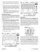
CARE AND MAINTENANCE
Periodically, visually inspect the cap terminals and rotor tip for
wear and look for traces of carbon tracking where spark scatter
occurs. Check your spark plug wires for burns or tears. It is
also recommended to periodically test the resistance of the
wires. See
Figure 10
for an exploded view of the distributor
and its parts.
Figure 8 - Modified Distributor Caps Figure 9 - Rotor Phasing with Timing Control
Figure 10 - Typical Pro-Tuner Distributor (3615 Shown)
Edelbrock Corporation • 2700 California St. • Torrance, CA 90503
Tech-Line: 1-800-416-8628 • E-Mail: Edelbrock@Edelbrock.com