Monticello TM Made in the USA 8’ x 8’ Greenhouse Assembly Instructions 071812 10 YEAR WARR ANT Y Customer Service: (877) 373-3078 Email: customerservice@risww.
Introduction Thank you for purchasing your MonticelloTM 8x8 Greenhouse. The Monticello line is proudly made in the USA by a leading commercial greenhouse maker using the same professional grade materials and design. The frame is constructed with the highest quality extruded aluminum with lead free powder-coated paint. The panels are professional grade 8mm twin wall polycarbonate selected for their insulation and durability.
Safety Advice Table of Contents The greenhouse must be positioned and fixed on a flat level surface. Dispose of all plastic bags safely. Keep them out of the reach of small children. Keep children and pets away from the assembly area until the work is completed. Always wear work shoes, gloves and safety goggles when working. Some of the parts have sharp edges and burs. Use extreme caution when handling. Do not lean against or push the greenhouse during assembly.
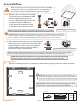
Constructing a Wood Platform ! IMPORTANT: It is very important to begin with a level surface. Check your foundation to ensure it is level at every point. If you are not building on a wood deck, we recommend constructing a wood platform so you can properly secure the greenhouse. You must assure your foundation is square and level before beginning assembly. After choosing a location, proper preparation of the site is essential. The site must be level.
List of Parts The greenhouse is shipped in four cartons. These cartons are heavy. Use care when lifting them. Some parts have sharp edges. Use extreme caution when handling. Wear proper safety gear including work shoes, gloves and safety goggles. Keep children and pets away until assembly is complete. Finish assembling the roof in one session. Do not leave the roof unattended until it is completely assembled. Place all like parts together in a staging area.
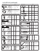
List of Parts (continued) WARNING: Use extreme caution when handling panels with cut edges. The corners are sharp.
List of Parts (continued) Connectors Hardware QTY QTY S-1 C-1 C-2 Trim Plates 4 2 Steps 5,6 Step 7 QTY B-6 2 Step 5 49 ⅜” G-4 4 Step 8 Step 9 4 S-2A 239 S-2B 239 S-2C 239 Steps 1,2,3,4,5, 6,7,810,11 S-3 4 Step 10 S-4 50 Steps 1,11 S-5A 1 Step 7 S-5B 1 Step 8 S-2C 1 Step 8 S-6 2 Step 9 QTY Included Tools T-1 1 Steps 8,9,10,11 T-2 1 Steps 1,2,3,4,5, 6,7,8,10 T-3 1 Steps 2,3,4 T-4 1 Step 8 Phillips Screwdriver QTY Door Parts 37 ½” D-1L 1 Step 10
Assemble Base Make certain the pieces are in the correct positions before assembling. Carefully follow the order of assembly to ensure an easy installation. Wear proper safety gear including work shoes, gloves and goggles. 1.1A We use a set screw and nut assembly system for ease of installation. With the hex shaped indent facing up, screw S-2B threaded part into S-2A nut until it is flush with bottom of nut. When the assembly is flush it will slide easily in the bolt tracks.
1.3 Separate profiles to install set screws into inside and outside bolt tracks. Some of the set screws will be secured in this step. Most are secured in later steps. They are difficult to install after the base is assembled. Pay careful attention to ensure you have the correct number of set screws in the correct bolt track in each profile. The profiles have different amounts of screws on the inside and outside bolt tracks. The chart and illustration below show the set screw placement.
1.4A Make certain side profiles are straight and flush. Adjust position of set screws in inner bolt track at front of profile to fit holes in B-5 connector. Center connector over seam for maximum hold. Secure using five bolts. Repeat on outer bolt track to install three remaining B-5 connectors at back and sides. B-5 B-8 B-5 B-5 BACK IMPORTANT: One B-5 connector is installed on inside front. Remaining B-5 connectors are installed on outside back and sides. B-8 corner connectors are installed on inside.
Assemble Right Wall Make certain the pieces are in the correct positions before assembling. Carefully follow the order of assembly to ensure an easy installation. Wear proper safety gear including work shoes, gloves and goggles. Prepare needed set screws as shown in step 1.1A NOTE: Have the hex shaped indent facing up. Screw in until it is flush with bottom of nut so it slides easily into bolt tracks. After inserting into bolt track, screw in until it holds in place. 2.1A Prepare two F-7 corner profiles.
2.2A Begin at front right corner. Remove plastic film from both sides of one W-1 panel. Fit panel into channel in base, placing side marked “ UV Resitant” facing outside. The panels will help hold the profiles up during assembly. 2.2B Place F-7 corner profile on base, fitting panel into channel. Slide set screws into base so they line up. Fit B-3 connector on each side. 2.2C Secure with four S-2C bolts. F-7 B-3 B-3 NOTE: VIEWS ARE FROM OUTSIDE. 2.3A Continue working from inside.
2.5A Prepare two G-1 gutter profiles by sliding four set screws into bottom bolt track. Hand tighten each end set screw to hold in place. G-1 G-1 2.5B Prepare one G-2 gutter profile with five set screws. Slide set screws into bottom bolt track. Hand tighten G-2 end set screw to hold in place. Profile QTY 25½” S-2A S-2B 2.6A 13 13 48½” G-1 2 G-2 1 Working from inside, place G-1 and G-2 gutter profiles, fitting top edge of W-1 panels into channels of gutters.
2.7A The gutters are secured together using B-5 connectors and attached to side profiles using B-3 connectors on the outside of the greenhouse. The B-3 connector uses the set screw in the center hole of B-5 connectors at seams. Loosen and slide set screws to line up with connectors making sure the seams line up and the gutters remain straight. 2.7B Begin at the three seams and arrange set screws so middle screw is centered. Fit B-5 connector onto gutter and hold in place using the two end bolts.
Assemble Back Wall Make certain the pieces are in the correct positions before assembling. Carefully follow the order of assembly to ensure an easy installation. Wear proper safety gear including work shoes, gloves and goggles. Prepare needed set screws as shown in step 1.1A NOTE: Have the hex shaped indent facing up. Screw in until it is flush with bottom of nut so it slides easily into bolt tracks. After inserting into bolt track, screw in until it holds in place. 3.1A Prepare one F-7 corner profile.
3.2A Working from inside, remove plastic film from both sides of one W-1 panel. Fit panel into channel in base and corner profile, placing side marked “ UV Resitant” facing outside. IMPORTANT: The panels expand and contract depending on the temperature. To ensure proper placement, use the 23 inch spacer included with the tools. 3.2B Place 23 inch spacer on base next to F-7 corner profile. Fit panel into channel in F-1 profile and slide F-1 profile against spacer to ensure proper placement.
3.4 The two sets of F-6 and F-10 profiles fit on top of W-1 panels. Line up bottom bolt channels with top edge of F-1 and F-7 vertical profiles. Profiles will fit snugly. 3.4A Working from inside right corner, place F-6 profile with mitered end next to corner and angled edge facing up onto corner W-1 panel. F-6 profile fits snugly between F-7 corner profile and F-1 wall profiles. F-6 G-1 F-1 3.4B Continue along back wall. Place first F-10 profile on next W-1 panel.
Assemble Back Wall Make certain the pieces are in the correct positions before assembling. Carefully follow the order of assembly to ensure an easy installation. Wear proper safety gear including work shoes, gloves and goggles. Prepare needed set screws as shown in step 1.1A NOTE: Have the hex shaped indent facing up. Screw in until it is flush with bottom of nut so it slides easily into bolt tracks. After inserting into bolt track, screw in until it holds in place. 3.1A Prepare one F-7 corner profile.
3.2A Working from inside, remove plastic film from both sides of one W-1 panel. Fit panel into channel in base and corner profile, placing side marked “ UV Resitant” facing outside. IMPORTANT: The panels expand and contract depending on the temperature. To ensure proper placement, use the 23 inch spacer included with the tools. 3.2B Place 23 inch spacer on base next to F-7 corner profile. Fit panel into channel in F-1 profile and slide F-1 profile against spacer to ensure proper placement.
Assemble Left Wall Make certain the pieces are in the correct positions before assembling. Carefully follow the order of assembly to ensure an easy installation. Wear proper safety gear including work shoes, gloves and goggles. Prepare needed set screws as shown in step 1.1A NOTE: Have the hex shaped indent facing up. Screw in until it is flush with bottom of nut so it slides easily into bolt tracks. After inserting into bolt track, screw in until it holds in place. 4.1A Prepare one F-7 corner profiles.
4.2A Continue working from inside back left corner. Remove plastic film from both sides of one W-1 panel. Fit panel into channel in base and corner profile, placing side marked “ UV Resistant” facing outside. IMPORTANT: The panels expand and contract depending on the temperature. To ensure proper placement, use the 23 inch spacer included with the tools. 4.2B Place 23 inch spacer on base next to F-7 corner profile.
4.4A Prepare two G-1 gutter profiles by sliding four set screws into bottom bolt track. Tighten each end set screw to hold in place. G-1 G-1 4.4B Prepare one G-2 gutter profile with five set screws. Slide set screws into bottom bolt track. Tighten end set screw to hold in place. G-2 Profile QTY 25½” S-2A S-2B 4.5A 13 13 48½” G-1 2 G-2 1 Working from inside, place G-1 and G-2 gutter profiles, fitting top edge of W-1 panels into channels of gutters.
4.6A The gutters are secured together using B-5 connectors and attached to side profiles using B-3 connectors on the outside of the greenhouse. The B-3 connector uses the set screw in the center hole of B-5 connectors at seams. Loosen and slide set screws to line up with connectors making sure the seams line up and the gutters remain straight. 4.6B Begin at the three seams and arrange set screws so middle screw is centered. Fit B-5 connector onto gutter and hold in place using the two end bolts.
Assemble Front Wall and Gable Make certain the pieces are in the correct positions before assembling. Carefully follow the order of assembly to ensure an easy installation. Wear proper safety gear including work shoes, gloves and goggles. Prepare needed set screws as shown in step 1.1A NOTE: Have the hex shaped indent facing up. Screw in until it is flush with bottom of nut so it slides easily into bolt tracks. After inserting into bolt track, screw in until it holds in place. 5.
5.3A Working from inside front left corner, remove plastic film from both sides of one W-1 panel. Fit panel into channel in base and corner profile, placing side marked “ UV Resistant” facing outside. IMPORTANT: The panels expand and contract depending on the temperature. To ensure proper placement, use the 23 inch spacer included with the tools. 5.3B Place 23 inch spacer on base next to F-7 corner profile.
5.4A Working from inside front right corner, install F-1 profile next to W-1 panel. Place 23 inch spacer on base next to F-7 corner profile and slide F-1 profile against spacer to ensure proper placement. IMPORTANT: The panels expand and contract depending on the temperature. To ensure proper placement, use the 23 inch spacer included with the tools. F-1 W-1 W-1 F-7 5.4B Fit B-3 connector and secure with two S-2C bolts. spacer tool F-1 B-3 NOTE: Panels will not fit completely to end of channels.
5.5 The door frame is 65¼” high from the base. To avoid adjusting the placement after assembly, prepare door frame using the exact measurements listed in these steps. 5.5A Prepare one F-4 profile. Slide two set screws into bolt track and position as shown. F-4 5.5B Prepare one F-5 profile. Slide four set screws into bolt tracks and position as shown. F-5 5.5C Place one end of F-4 profile against F-5 profile on flat level surface.
5.6A Working from inside, remove plastic film from both sides of two W-3 panels. Fit each panel into channels in profiles, placing side marked “ UV Resistant” W-3 facing outside. W-3 WARNING: The corners of W-3 panels are sharp. Use extreme caution when handling. 5.6B Continue working from intside, install door frame. Loosen set screws on ends of F-5 profile and adjust position to fit holes in B-2 F-5 connector. 5.6C Secure with two bolts. Ensure height to base is 65¼”.
5.9A Prepare two F-7 corner profiles. Slide three set screws into the same bolt track, two on one end and one on other end of profile. Position one set screw in center of profile. It will be used in a later step. Tighten each set screw to F-7 hold in place. F-7 5.9B From outside fit F-7 profiles into each side of front. Begin with either side. Arrange F-7 profile so channel lines up with tops of panels and the set screws are facing out.
Assemble Back Wall Make certain the pieces are in the correct positions before assembling. Carefully follow the order of assembly to ensure an easy installation. Wear proper safety gear including work shoes, gloves and goggles. Prepare needed set screws as shown in step 1.1A NOTE: Have the hex shaped indent facing up. Screw in until it is flush with bottom of nut so it slides easily into bolt tracks. After inserting into bolt track, screw in until it holds in place. 6.1A Prepare two F-7 corner profiles.
6.2 From inside, add connector B-7 to each corner. Secure each with two bolts. G-1 F-6 F-7 B-7 IMPORTANT: Bolt track of F-6 front profile is lower than bolt track of G-1 gutter profile. Connector NOTE: VIEWS FROM INSIDE. QTY B-7 S-2C 2 4 6.3A Continue working from inside. Line up F-2 and F-3 profiles with F-1 profiles as shown. Loosen set screws and adjust position to fit holes in B-1 connectors. Make sure profiles are straight. 6.3B Secure with bolt in each B-1 connector.
6.5 Continue working from outside to install panels a shown. Remove plastic film from both sides of two W-3 and two W-4 panels. Fit each W-3 panel into channel in profiles, placing side marked “UV Resistant” facing outside. W-4 W-4 W-3 NOTE: VIEW FROM OUTSIDE. WARNING: The corners of W-3 and W-4 panels are sharp. Use extreme caution when handling. Panel QTY 24” x 15 ¼” NOTE: Panels will not fit completely to end of channels. There will be some space to allow for temperature changes. 6.
Assemble Roof Ridge Make certain the pieces are in the correct positions before assembling. Carefully follow the order of assembly to ensure an easy installation. Wear proper safety gear including work shoes, gloves and goggles. Prepare needed set screws as shown in step 1.1A NOTE: Have the hex shaped indent facing up. Screw in until it is flush with bottom of nut so it slides easily into bolt tracks. After inserting into bolt track, screw in until it holds in place. 7.1 Prepare the two R-1 roof profiles.
7.2A Use two people and a step ladder. Place step ladder inside greenhouse. Have one person inside greenhouse supporting ridge as you slide it into position. Avoid touching top of front and back of greenhouse until each end is flush with ends of front and back profiles. WARNING: Use two people to install roof ridge. Place ladder in inside of greenhouse. One person will stand on the ladder holding the ridge until it is in the proper position and secured in place. R-1 R-1 7.
Assemble Roof Make certain the pieces are in the correct positions before assembling. Carefully follow the order of assembly to ensure an easy installation. Wear proper safety gear including work shoes, gloves and goggles. Prepare needed set screws as shown in step 1.1A NOTE: Have the hex shaped indent facing up. Screw in until it is flush with bottom of nut so it slides easily into bolt tracks. After inserting into bolt track, screw in until it holds in place. 8.1A Prepare all profiles for roof.
8.2 The roof panels are installed in the sections shown below. Use two people and a step ladder to assemble the roof. Place step ladder inside greenhouse. Have one person stand on ladder inside and guide panel into channels in roof ridge and corner profiles. The other person supports the end of the panel from the outside. 1 1 3 3 3 2 2 Section 1: Back two W-1 panels Section 2: Front two W-1 panels Section 3: Middle three W-1 panels Section 4: W-2 panel 4 WARNING: Use two people to install roof.
8.3A Working from back right corner, remove plastic film from both sides of one W-1 panel. With side marked “ UV Resistant” facing outside, fit top end of panel into channel in R-1 roof ridge near corner. Push panel into roof ridge channel until the other end rests on gutter ledge and then slide towards F-7 corner profile. Repeat to install W-1 panel in back left corner. R-1 F-7 W-1 G-1 F-7 R-1 R-1 W-1 F-7 W-1 W-1 F-7 G-1 W-1 G-1 NOTE: VIEWS FROM OUTSIDE. 8.
8.4A Continue installing roof working from front right corner, remove plastic film from both sides of one W-1 panel. With side marked “ UV Resistant” facing outside, fit top end of panel into channel in R-1 roof ridge near corner. Push panel into roof ridge channel until the other end rests on gutter ledge and then slide towards F-7 corner profile. Repeat to install W-1 panel in front left corner. R-1 F-7 W-1 G-1 F-7 G-1 W-1 NOTE: VIEWS FROM OUTSIDE. 8.
8.5 Remove bungee cord and continue working from back to install section four. You will be installing one panel on the right with the F-1 profile next to it. Then you will install the two remaining panels on the left. The final F-1 profile slides up from the outside at the gutter to the ridge. You will need extra help to hold the two panels in position. Use dish soap with water to help lubricate the panel edges. 8.5A Remove plastic film from both sides of one W-1 panel.
8.5D From the inside, have one person lift the bottom corners of the two panels where they meet. From the outside have the other person hold and position F-1 profile so both panels fit in channels on sides of F-1 profile. Slide the F-1 profile up towards the roof ridge. As the profile moves up, have the person on the inside guide it into place. NOTE: Use dish soap with water on edges of panels to help slide F-1 profile into place. F-1 W-1 W-1 F-1 F-1 W-1 W-1 NOTE: VIEWS FROM OUTSIDE. F-1 8.
8.7 Have one person stand outside the greenhouse to observe the position of the roof ridge while the other person installs the B-9 brace. The set screws should be in the correct position, but if the roof is not completely straight, loosen the set screws and adjust the brace to raise or lower the roof line. Secure with two bolts. B-9 Brace QTY B-9 S-2C NOTE: VIEWS FROM INSIDE. 8.8 1 2 The G-4 trim plates snap into G-1 and G-2 gutter profiles to hold roof panels in place.
Install Roof Vents Make certain the pieces are in the correct positions before assembling. Carefully follow the order of assembly to ensure an easy installation. Wear proper safety gear including work shoes, gloves and goggles. 9.1A Unpack contents of Automatic Window Opener. Screw adjusting knob partially into threaded end of cylinder. Do NOT tighten. adjusting knob cylinder cylinder 9.1B Fit piston rod connected to arm B into end of cylinder. Turn cylinder so holes next to adjusting knob are visible.
9.2C Screw two S-1 screws through V-2 panel. Line up gripping channel on other side. Continue to screw until secure. Do not over tighten as it may damage the vent. V-2 gripping channel V-2 S-1 Connector NOTE: VIEW FROM INSIDE. 9.3A QTY NOTE: VIEW FROM OUTSIDE. S-1 Gripping Channel 2 QTY 1 From inside, hold Window Opener closed against vent. Slide vent at an angle through opening in roof panels. Hook top lip of vent onto curve V-2 in ridge profile R-1. R-1 R-1 V-2 NOTE: VIEWS FROM FRONT.
Install Doors Make sure the pieces are in the correct positions before assembling. Carefully follow the order of assembly to ensure an easy installation. Wear proper safety gear including work shoes, gloves and goggles. IMPORTANT: The door and door track are different for the left and right sides. Study the diagrams before installing to ensure you have the parts correctly placed. 10.1A From outside, prepare to install right and left door tracks.
10.2 From the inside, position set screw three inches from right and left F-1 door frame profiles. Install B-3 connector as shown and secure each with a bolt. F-1 B-3 Connector B-3 S-2C NOTE: These connectors act as door guides and will be wrapped in sealant tape in step 10.3B NOTE: VIEW FROM INSIDE. 10.3A QTY 2 2 Working from the outside, apply the D-4 door sealant tape to the outside of F-1 profiles that make up the door frame. This tape acts as insulation.
10.4A To install D-2L factory assembled door, remove the bolt attaching left door track D-1L to F-7 profile. With the wheels facing inside, line up so they roll into the left door track. As you roll the door along the track, make certain it slides inside the B-3 door guide installed in step10.2. Continue to roll door until it stops next to the bolt at the center. Secure using the bolt you removed. L2-D D-1L B-3 D-2L D-2L D-2R D-1L D-2L NOTE: VIEWS FROM OUTSIDE. 10.4B Repeat step 10.
Secure to Platform Make certain the pieces are in the correct positions before assembling. Carefully follow the order of assembly to ensure an easy installation. Wear proper safety gear including work shoes, gloves and goggles. Prepare needed set screws as shown in step 1.1A NOTE: Have the hex shaped indent facing up. Screw in until it is flush with bottom of nut so it slides easily into bolt tracks. After inserting into bolt track, screw in until it holds in place. 11.